Method for manufacturing magnetoresistance element and apparatus for manufacturing magnetoresistance element

A magnetoresistance effect element and manufacturing method technology, applied in the manufacture/processing of electromagnetic devices, resistors controlled by magnetic fields, etc., can solve the problems of lower MR ratio and difficulty in achieving low RA and high MR ratio at the same time

Inactive Publication Date: 2009-03-25
CANON ANELVA CORP
View PDF1 Cites 19 Cited by
  • Summary
  • Abstract
  • Description
  • Claims
  • Application Information

AI Technical Summary

Benefits of technology

This patented technology allows magnetic resistance elements made up of an alloy called Magnetosetronium Oxide (MGO) to have improved performance when exposed to different types of gases like O2 or H2. By creating this special structure within the membrane-forming chambers used by these materials, it becomes possible to achieve both higher values of their resistivity at lower temperatures compared to traditional structures while maintaining good stability over time.

Problems solved by technology

The patent text discusses the use of magnetoresistance effect elements in MRAM and magnetic head sensors. These elements consist of two ferromagnetic layers separated by an insulator layer. The resistance of the element changes depending on the alignment of the magnetization directions of the ferromagnetic layers. To detect the direction of an external magnetic field, it is important to have a high magnetoresistance ratio (MR ratio). However, when the element size is small, it becomes challenging to achieve both a low resistance and a high MR ratio. The text highlights the problem of decreasing MR ratio when the thickness of the insulator layer is reduced to reduce resistance.

Method used


Image

  • Method for manufacturing magnetoresistance element and apparatus for manufacturing magnetoresistance element
  • Method for manufacturing magnetoresistance element and apparatus for manufacturing magnetoresistance element
  • Method for manufacturing magnetoresistance element and apparatus for manufacturing magnetoresistance element

Examples


Embodiment Construction

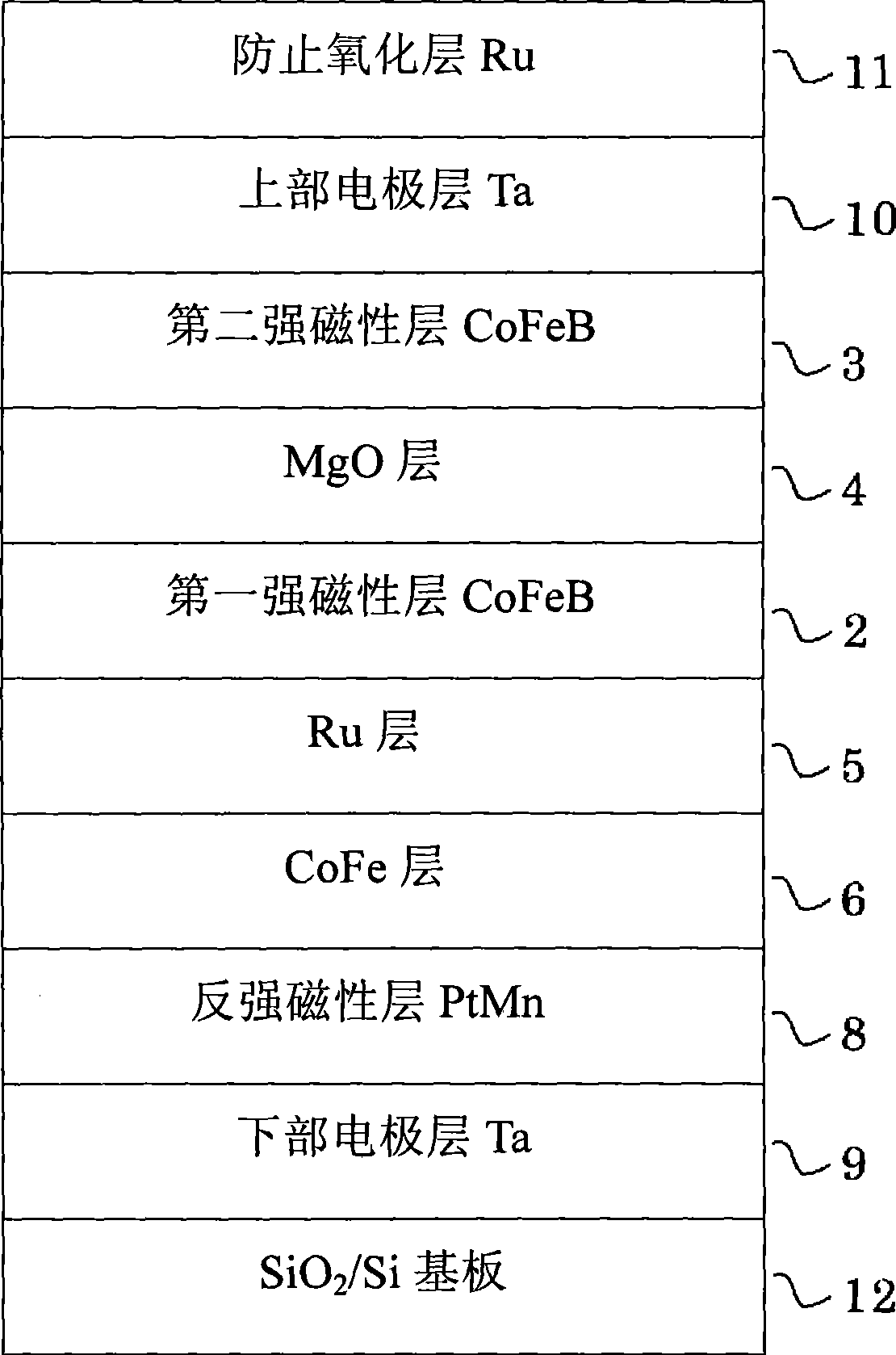
[0081] refer to figure 1 , figure 2 as well as image 3 , to illustrate the first embodiment of the present invention. figure 1 It is a diagram showing an example of the thin film structure of the magnetoresistance effect element having the MgO insulator layer manufactured in the first example.

[0082] figure 1 In, SiO is formed on the surface 2 On a Si (silicon) substrate 12 made of (silicon dioxide), a lower electrode layer 9 (thickness 10 nm) made of Ta (tantalum) and an antiferromagnetic layer 8 (film thickness 10 nm) made of PtMn (platinum manganese) are laminated. 15nm thick), CoFe (cobalt iron) layer 6 (film thickness 2.5nm), Ru (ruthenium) layer 5 (film thickness 0.85nm), first ferromagnetic layer 2 (film thickness 3nm) formed by CoFeB (cobalt iron boron) ), an insulator layer 4 (thickness 1.0nm) made of MgO (magnesium oxide), a second ferromagnetic layer 3 (thickness 3nm) made of CoFeB (cobalt iron boron), and an upper electrode made of Ta (tantalum) layer 10 ...


PUM


Abstract

This invention provides a method for manufacturing a magnetoresistance element having a high MR ratio despite low RA and an apparatus for manufacturing a magnetoresistance element. A magnetoresistance element comprising an MgO (magnesium oxide) layer between a first ferromagnetic layer and a second ferromagnetic layer is produced by forming the MgO layer within a film forming chamber in which a material having a high gettering effect against oxidizing gases such as oxygen and water is applied onto the surface of constituent members, provided within the MgO layer forming chamber, for example, a film forming chamber inner wall (37) within a first film forming chamber (21), an inner wall in a deposition-preventive shield (36), a partition plate (22), and a shutter. The material having a high gettering effect may be a material having an oxygen gas adsorption energy value of not less than 145 kcal/mol. Ta (tantalum) as a material for constituting the magnetoresistance element is particularly preferred.

Description


Claims


Application Information

Patent Timeline
Owner CANON ANELVA CORP
Why Eureka
Try Eureka