Braze system and method for reducing strain in a braze joint

a braze joint and strain reduction technology, applied in the direction of manufacturing tools, solvents, transportation and packaging, etc., can solve the problems of catastrophic failure of the joint, thermal mismatch between ceramic and metal materials, and zirconium also being expected to have limited utility

Inactive Publication Date: 2003-12-25
SANDIA NAT LAB
View PDF0 Cites 123 Cited by
  • Summary
  • Abstract
  • Description
  • Claims
  • Application Information

AI Technical Summary

Benefits of technology

[0009] It is yet another object of this invention to provide a means for overcoming large mechanical stress is caused by joining materials having large differences in coefficients of thermal expansion.
[0011] It is still another object of the present invention to provide a braze assembly which is capable of absorbing mechanical strain generated when joining materials having dissimilar thermal characteristics.

Problems solved by technology

A major problem in joining ceramics to metals is the thermal mismatch between the ceramic and metal materials.
Thermal mismatch causes significant residual stress in the ceramic, leading to catastrophic failure of the joint.
Finally, the zirconium also would be expected to have limited utility due to the pyrophoric nature of the powdered forms of this material.

Method used


Image

  • Braze system and method for reducing strain in a braze joint
  • Braze system and method for reducing strain in a braze joint
  • Braze system and method for reducing strain in a braze joint

Examples


Embodiment Construction

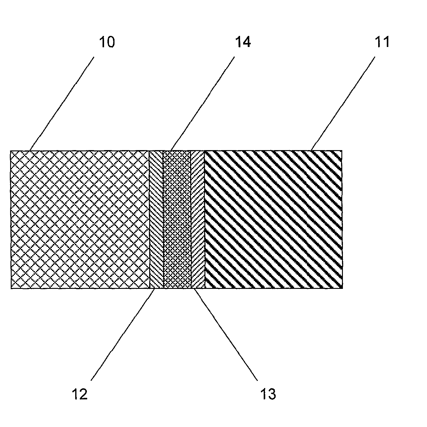
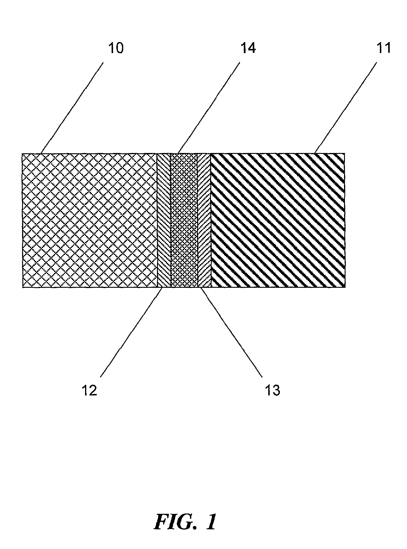
[0023] A braze joint utilizing the braze system of the present invention is shown schematically in FIG. 1 and was prepared as described below.

[0024] A wafer 14 comprising the intermediate composite material was prepared as described above using finely divided tungsten particles (-325 US Screen Mesh) dispersed into a quantity of copper. The intermediate composite was then cooled and formed into a billet from which wafers with a thickness of about 1 mm were cut. Wafer 14 was then sandwiched between layers 12 and 13 of an appropriate braze alloy and the ensemble sandwiched between a first test piece 10 of 94% alumina ceramic, and a second test piece 11 of INCONEL 625 nickel alloy. The entire assembly was then held together in a braze fixture (not shown) for alignment and to apply modest pressure to the parts (about >150 kPa). Layer 12 comprised a so-called "active" braze alloy consisting essentially of gold with 16% nickel, 1.75% vanadium, and 0.8% molybdenum. Layer 13 can be the same ...


PUM

PropertyMeasurementUnit
weight fractionaaaaaaaaaa
diameteraaaaaaaaaa
thickaaaaaaaaaa

Abstract

A system for joining a pair of structural members having widely differing coefficients of thermal expansion is disclosed. A mechanically "thick" foil is made by dispersing a refractory metal powder, such as molybdenum, niobium, tantalum, or tungsten into a quantity of a liquid, high expansion metal such as copper, silver, or gold, casting an ingot of the mixture, and then cutting sections of the ingot about 1 mm thick to provide the foil member. These foil members are shaped, and assembled between surfaces of structural members for joining, together with a layer of a braze alloy on either side of the foil member capable of wetting both the surfaces of the structural members and the foil. The assembled body is then heated to melt the braze alloy and join the assembled structure. The foil member subsequently absorbs the mechanical strain generated by the differential contraction of the cooling members that results from the difference in the coefficients of thermal expansion of the members.

Description

[0002] 1. Field of the Invention[0003] This invention relates to a ceramic-metal composite article and fabrication method therefor. In particular, the invention relates to a system comprising a composite braze joint structure for joining members having very dissimilar coefficients of thermal expansion. Furthermore, the present invention relates to a composite braze joint for joining a metal and a ceramic member.[0004] 2. Description of the Prior Art[0005] A major problem in joining ceramics to metals is the thermal mismatch between the ceramic and metal materials. Thermal mismatch causes significant residual stress in the ceramic, leading to catastrophic failure of the joint. It is well known that to join materials having markedly different coefficients of thermal expansion and still provide a strong joint it is necessary to implement a means for reducing the strain which builds at the joint as the joined members cool. Ceramic-metal joints have used various joining methods, e.g. gla...

Claims


Application Information

Patent Timeline
Patent Type & Authority Applications(United States)
IPC IPC(8): B23K1/00B23K35/00B23K35/02B23K35/14B23K35/30
CPCB23K1/0016Y10T428/12535B23K35/004B23K35/0233B23K35/0238B23K35/3013B23K2203/18B32B2311/04B32B2311/22C04B37/026C04B2235/6581C04B2237/125C04B2237/343C04B2237/403C04B2237/405C04B2237/408Y10T428/12438Y10T428/12431B23K35/001B23K2103/02B23K2103/08B23K2103/18B23K2103/26B23K2103/52
Inventor CADDEN, CHARLES H.GOODS, STEVEN H.PRANTIL, VINCENT C.
Owner SANDIA NAT LAB
Why Eureka
Try Eureka