
Linear drive with a reduced axial force component, as well as a linear compressor and refrigerator

A linear compressor, linear drive technology, applied in the direction of electromechanical devices, electric components, magnetic circuit shape/style/structure, etc., can solve the problem that the back and forth motion cannot be controlled according to the required precision, the moving parts are difficult to drive, and the braking energy system Loss and other problems, to achieve the effect of easy control, reduced asymmetry, precise and efficient operation

Inactive Publication Date: 2009-03-25
BSH BOSCH & SIEMENS HAUSGERAETE GMBH
View PDF1 Cites 6 Cited by
  • Summary
  • Abstract
  • Description
  • Claims
  • Application Information

AI Technical Summary

Problems solved by technology

[0004] The problem with existing solutions is that the moving parts are difficult to drive precisely, especially their back and forth movement cannot be controlled with the required precision
Although such braking operations are effective in preventing compressor piston slamming, they are disadvantageous if the highest possible operating efficiency is desired, since the braking energy will be lost to the system

Method used


Image

  • Linear drive with a reduced axial force component, as well as a linear compressor and refrigerator
  • Linear drive with a reduced axial force component, as well as a linear compressor and refrigerator
  • Linear drive with a reduced axial force component, as well as a linear compressor and refrigerator

Examples


Embodiment Construction

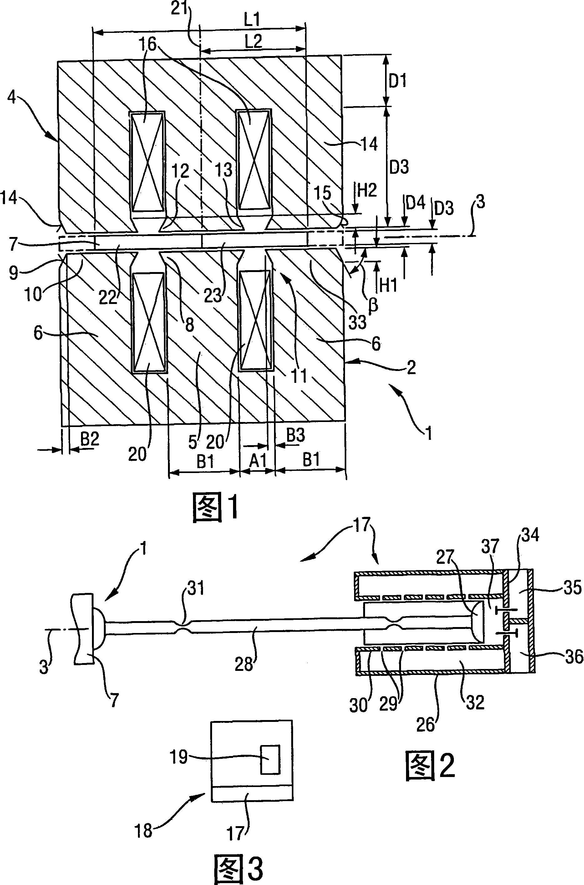
[0059] 1 shows a longitudinal section of a linear drive 1 according to the invention along the axis of motion 3 and along the coil axis 21 of the excitation coils 16 , 20 on the stator 2 . The linear drive 1 has a stator 2 and a moving part 7, and the moving part 7 moves oscillatingly back and forth along the axis 3 between two opposing points. The stator 2 has a magnetic field guiding core 4 with an inner leg 5 and two outer legs 6 each having a respective foot 8 , 33 extending approximately toward the moving part 7 . The inner foot 8 is arranged on the inner leg 5 and the outer foot 10 , 33 is arranged on the outer leg 6 . The feet 8 , 10 , 33 have inclined surfaces 9 and / or projections 12 , 13 . The inclined surface 9 can be implemented as a flat surface 14 or as a convexly curved surface 15 . The inner foot 8 has a first lug 12 and a second lug 13 each facing the adjacent outer foot 10 , 33 . The projections 12 , 13 are trapezoidal in longitudinal section along the axis...


PUM


Abstract

The invention relates to a linear drive (1) comprising a stator (2) and an axis (3), a rotor (7) which moves in a reciprocating manner, with the stator (2) having a magnetic field guide core (4) with legs (5, 6) with the legs (5, 6) each having a foot (8, 10) which extends essentially towards the rotor (7), with at least one foot (8, 10) having an inclined surface (9), or having a plurality of magnets (22, 23) which are arranged one above the other in the direction of the axis (3), with the respective lengths (L2) of the magnets (22, 23) along the axis (3) and the respective widths (B1) of the legs (5, 6) along the axis (3), and / or the respective distances (A1) between the legs (5, 6) along the axis (3) differing such that force components of the rotor 7 along the axis (3) are reduced when no current is found in the linear drive (1), as well as a linear compressor,; a refrigerator and a method for cooling and / or for compressing a fluid. The invention is distinguished in that undesirable force components along the axis (3) are reduced by the configuration of the foot (8, 10) with an inclined surface (9) and by a suitable choice of the lengths, widths and distances, thus allowing better open-loop and / or closed-loop control of the reciprocating movement of the rotor (7).

Description

technical field [0001] The invention relates to a linear drive comprising a stator and a moving part movable back and forth along an axis in the stator, said stator having a magnetizable magnetic field guiding core with legs each extending separately There is a foot generally towards moving parts; a linear compressor; a refrigeration device, in particular a refrigerator and / or freezer or air conditioning system; and a method for cooling items or compressing fluids. Background technique [0002] A linear drive with permanently energized moving parts is selectively moved by applying suitable currents to excitation coils on the stator to appropriately energize them. The coil magnetic field is guided by a magnetizable field-guiding core with poles and concentrated in the area around the moving part. [0003] DE69901586T2 discloses an electromagnetic linear actuator comprising a stator structure with two poles excited by at least one electrical winding. The moving member has a ...

Claims


Application Information

Patent Timeline
Patent Type & Authority Applications(China)
IPC IPC(8): H02K33/10H02K41/03H02K1/14
CPCH02K33/16H02K1/145
Inventor R·勒克莱因U·魏纳特
Owner BSH BOSCH & SIEMENS HAUSGERAETE GMBH
Learn More