
Solar hydraulic transmission device

A technology of hydraulic transmission device and solar energy, applied in solar thermal device, fluid pressure actuation device, solar thermal power generation and other directions, can solve the problems of short circuit accident, high cost, wire bite by mice, etc., and achieve high sensitivity, safe and reliable operation, low cost effect

Inactive Publication Date: 2009-04-01
叶梅坤
View PDF0 Cites 0 Cited by
  • Summary
  • Abstract
  • Description
  • Claims
  • Application Information

AI Technical Summary

Problems solved by technology

[0002] At present, some switches such as solar water heaters and chemical warehouses are all electric switches. Electricity is not a free energy source. At the same time, due to power outages, electrical equipment and lines are outdated, and rats biting lines cause short-circuit accidents, resulting in explosions or fires, which will cause loss of life or property. loss, in order to avoid these accidents and save electricity, it is best to use solar energy
The cylindrical heat exchange plate of the original solar hydraulic transmission device has the function of tracking solar energy, but the inner plate surface of the inner cavity cannot be illuminated by the sun, the sunny area is equal to the back sunny area, and the solar energy loss is large. The original cylindrical heat exchange plate It must be heated and bear the pulling force caused by ammonia, which increases the input of materials
Secondly, although the vacuum tube solar water heater that does not need a switch can make full use of solar energy, the cost is relatively high, which is not conducive to popularization.

Method used


Image

  • Solar hydraulic transmission device
  • Solar hydraulic transmission device

Examples


Embodiment Construction

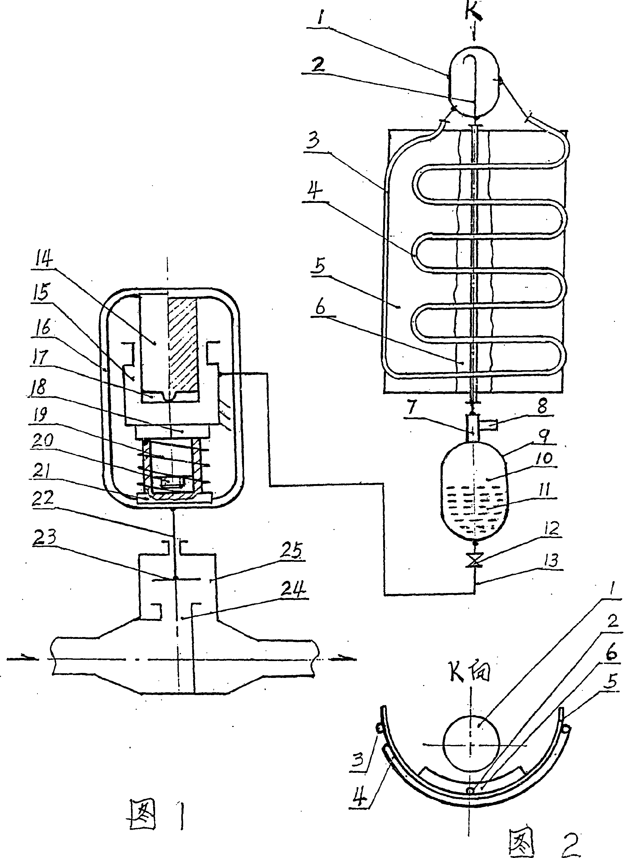
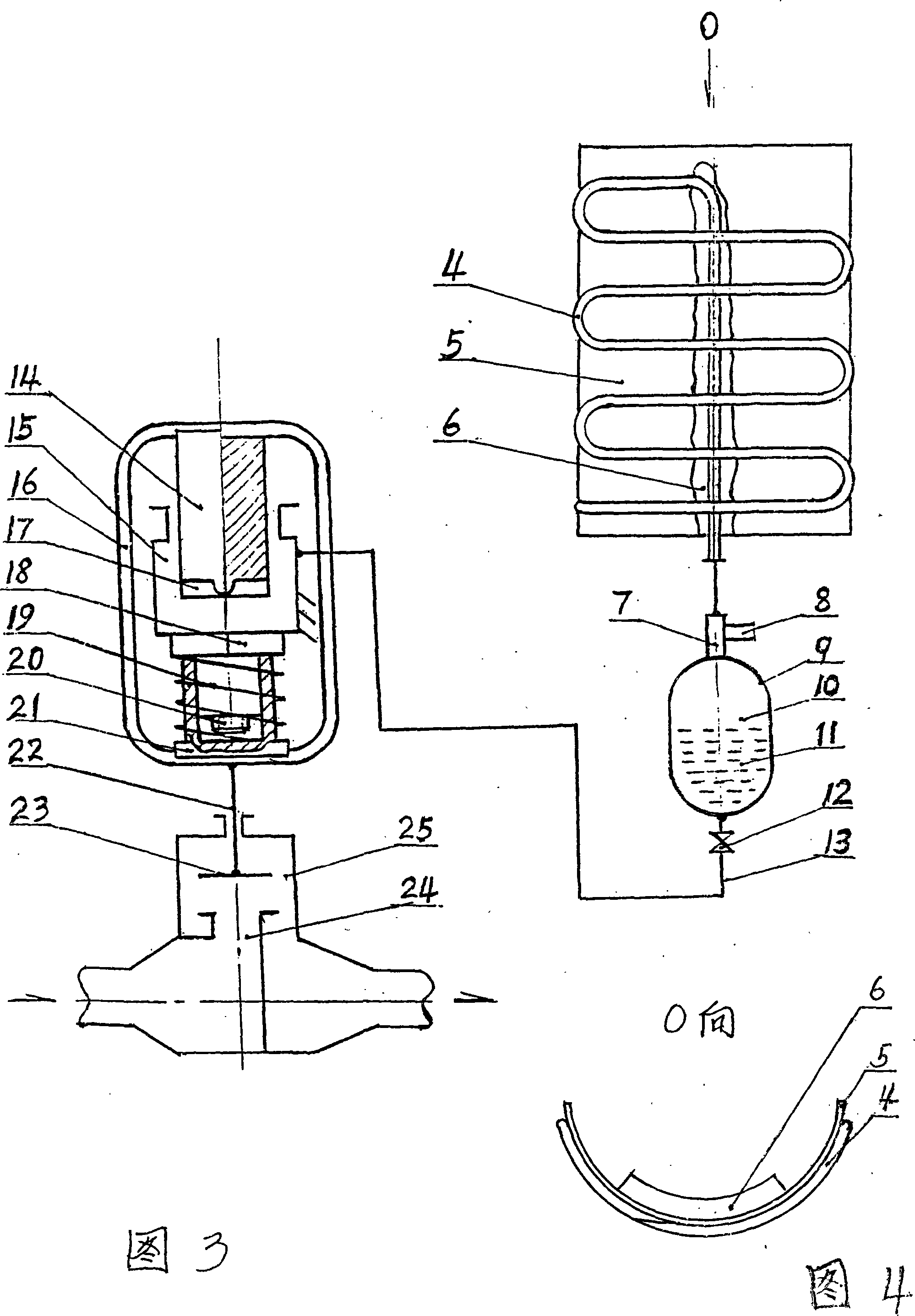
[0018] In the embodiment shown in Figures 1 and 2, the hydraulic separator [1] is installed above the tile-shaped heat exchange plate [5], and the serpentine heat exchange tube [4] is closely attached to the heat exchange plate [5]. The heat insulation layer [6] is pasted on the back of the exchange plate [5], the middle part of the hydraulic separator [1] is connected to the upper end of the serpentine heat exchange tube [4], and the lower end of the serpentine heat exchange tube [4] is connected to the infusion fluid The lower end of the pipe [3], the upper end of the infusion tube [3] is connected to the lower part of the liquid-gas separator [1]; the straight pipe section of the gas delivery pipe [2] with the barb air inlet end extends downward to the liquid-gas separator [1] ] The bottom of the inner cavity is drilled out, and continues to extend and connect with the safety valve seat [7] top by sticking to the tile-type heat exchange plate [5] back side. Safety valve sea...


PUM


Abstract

The invention relates to a solar-energy hydraulic transmission device which comprises a coil heat-exchange tube, a tile-type heat-exchange plate, a heat insulating layer, a liquid-gas separator, an oil tank, an oil pipe, a ring-pull, a cylinder, a piston, a spring, an adjusting screw and a valve. The solar-energy hydraulic transmission device makes use of the function of solar energy to the heat-exchange tube and the heat-exchange plate and causes the containment of ammonia filled in the heat-exchange tube to be changed so as to generate oil pressure which causes the piston to drive a valve stem in the ring-pull, thereby controlling the on-off of the valve and guaranteeing the normal operation of a solar-energy water heater or the normal start-up of the on-off of the ventilation window of a warehouse. The solar-energy hydraulic transmission device use the function that the tile-type heat-exchange plate can be heated on both sides and use the heat insulating layer to remove the peak value of high pressure and to level up the valley value of low pressure; therefore, working pressure tends to smoothness, the operation is safe and liable, and the manufacturing cost is low. The solar-energy hydraulic transmission device can control the working pressure, realize the synchronal operation with the solar-energy water heater, and serves as a ventilation switch for the requiring of the indoor temperature control without electricity supply. When the room temperature reaches a certain degree, the solar-energy hydraulic transmission device can automatically open the windows to allow ventilation and give alarms.

Description

technical field [0001] The invention belongs to a hydraulic transmission device in mechanical engineering, in particular to a solar hydraulic transmission device. Background technique [0002] At present, some switches such as solar water heaters and chemical warehouses are all electric switches. Electricity is not a free energy source. At the same time, due to power outages, electrical equipment and lines are outdated, and rats biting lines cause short-circuit accidents, resulting in explosions or fires, which will cause loss of life or property. Loss, in order to avoid these accidents and save electricity, it is best to use solar energy. The cylindrical heat exchange plate of the original solar hydraulic transmission device has the function of tracking solar energy, but the inner plate surface of the inner cavity cannot be illuminated by the sun, the sunny area is equal to the back sunny area, and the solar energy loss is large. The original cylindrical heat exchange plate...

Claims


Application Information

Patent Timeline
Patent Type & Authority Applications(China)
IPC IPC(8): F15B15/00H01H35/18F24J2/00
CPCY02E10/40
Inventor 叶梅坤
Owner 叶梅坤
Features
  • Generate Ideas
  • Intellectual Property
  • Life Sciences
  • Materials
  • Tech Scout
  • Unparalleled Data Quality
  • Higher Quality Content
  • 60% Fewer Hallucinations
Learn More