Supercharge Your Innovation With Domain-Expert AI Agents!

Air conditioner

A technology for air conditioners and wind direction boards, which is applied in air conditioning systems, space heating and ventilation, and home heating, etc., can solve problems such as damage to appearance, no mention of downward airflow direction, no mention of airflow, etc., to maintain the appearance. Effect

Active Publication Date: 2010-07-21
HITACHI JOHNSON CONTROLS AIR CONDITIONING INC
View PDF2 Cites 0 Cited by
  • Summary
  • Abstract
  • Description
  • Claims
  • Application Information

AI Technical Summary

Problems solved by technology

[0014] Although Patent Document 2 describes the case where the air flow is blown downward, it does not mention the case where the air flow is blown upward.
Moreover, since there are three wind direction boards to narrow the air passage, especially in the case of using thick blade-shaped wind direction boards, the space between the upper and lower wind direction boards and the upper wall of the blowing air duct becomes narrow during air-conditioning operation, and the wind speed increases. Increase the ventilation resistance of this part and increase the noise
[0015] Although Patent Document 3 describes the case where the airflow is blown upward or horizontally, it does not mention the case where the direction of the airflow is downward as in heating operation.
And, of course, there is no mention of the warping direction of the louver when the airflow is blown downward.
[0016] In Patent Document 4, since there is a stepped portion on the wind direction plate, even if the air outlet is closed during a stop, the stepped portion is conspicuous, impairing the appearance when stopped

Method used


Image

  • Air conditioner
  • Air conditioner
  • Air conditioner

Examples


Embodiment Construction

[0037] Hereinafter, embodiments of the present invention will be described using the drawings. The same symbols in the drawings indicate the same or equivalent.

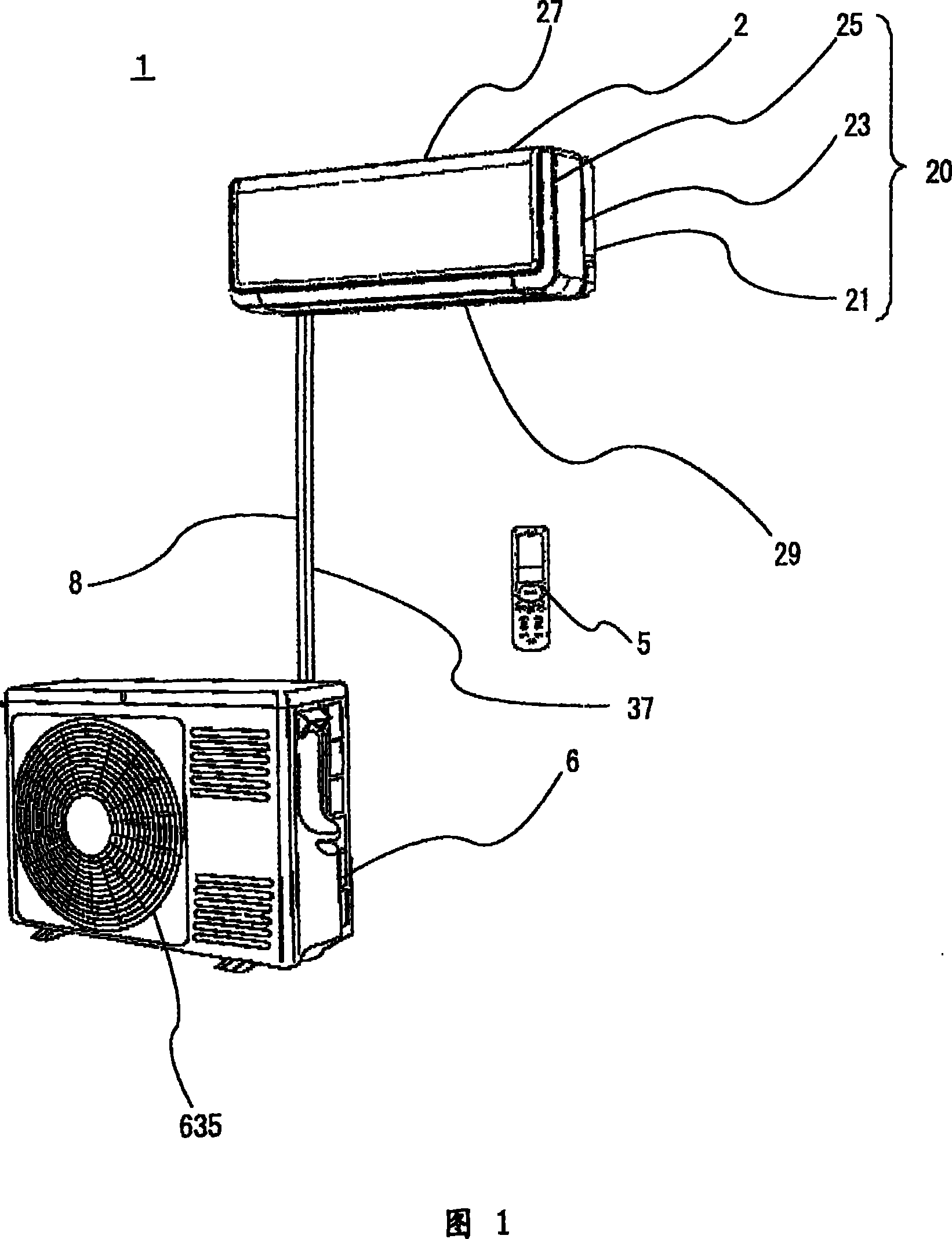
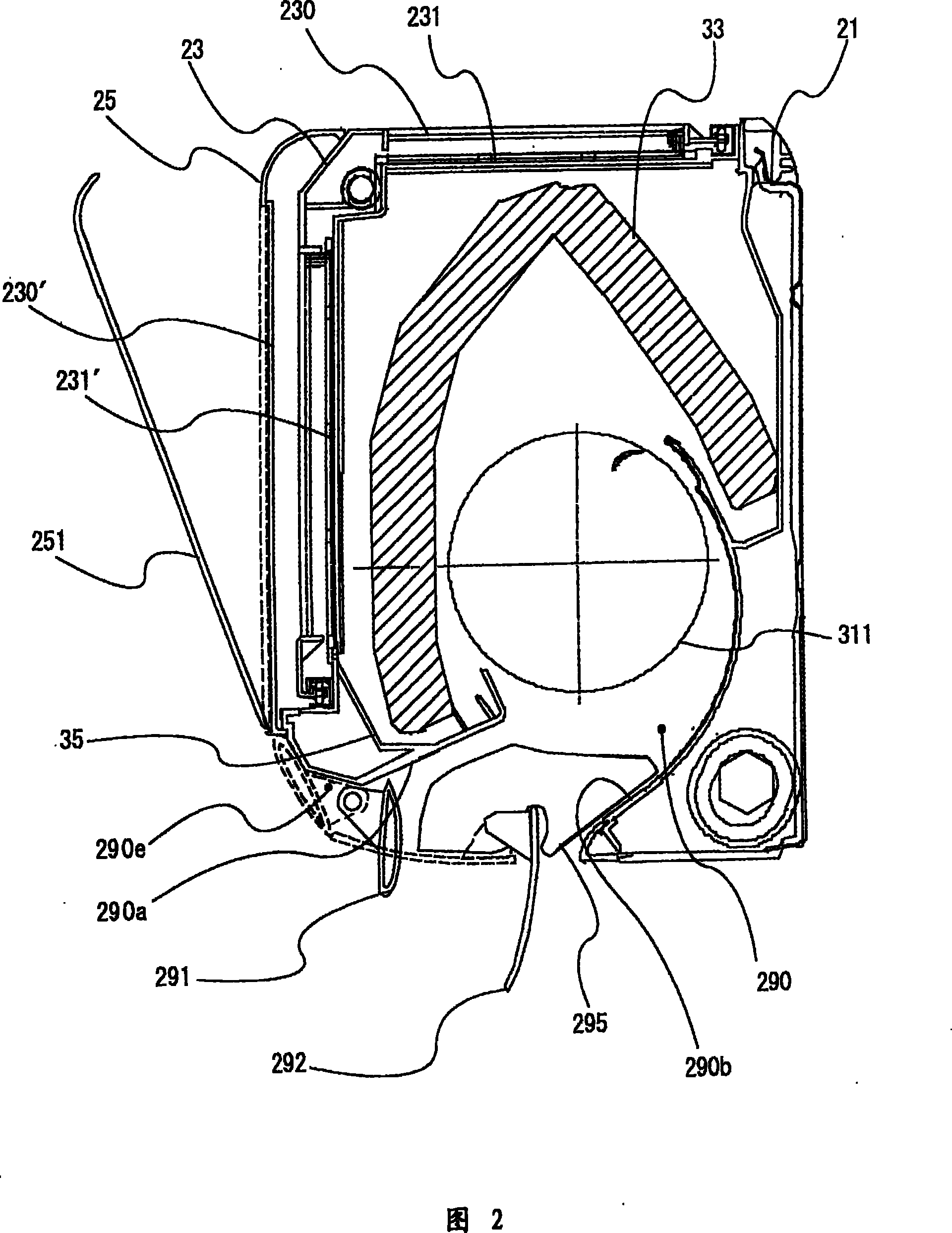
[0038] First, use figure 1 , figure 2 The overall configuration of the air conditioner will be described. figure 1 It is a block diagram of the air conditioner of an Example. figure 2 It is a side sectional view of the indoor unit of the same air conditioner.

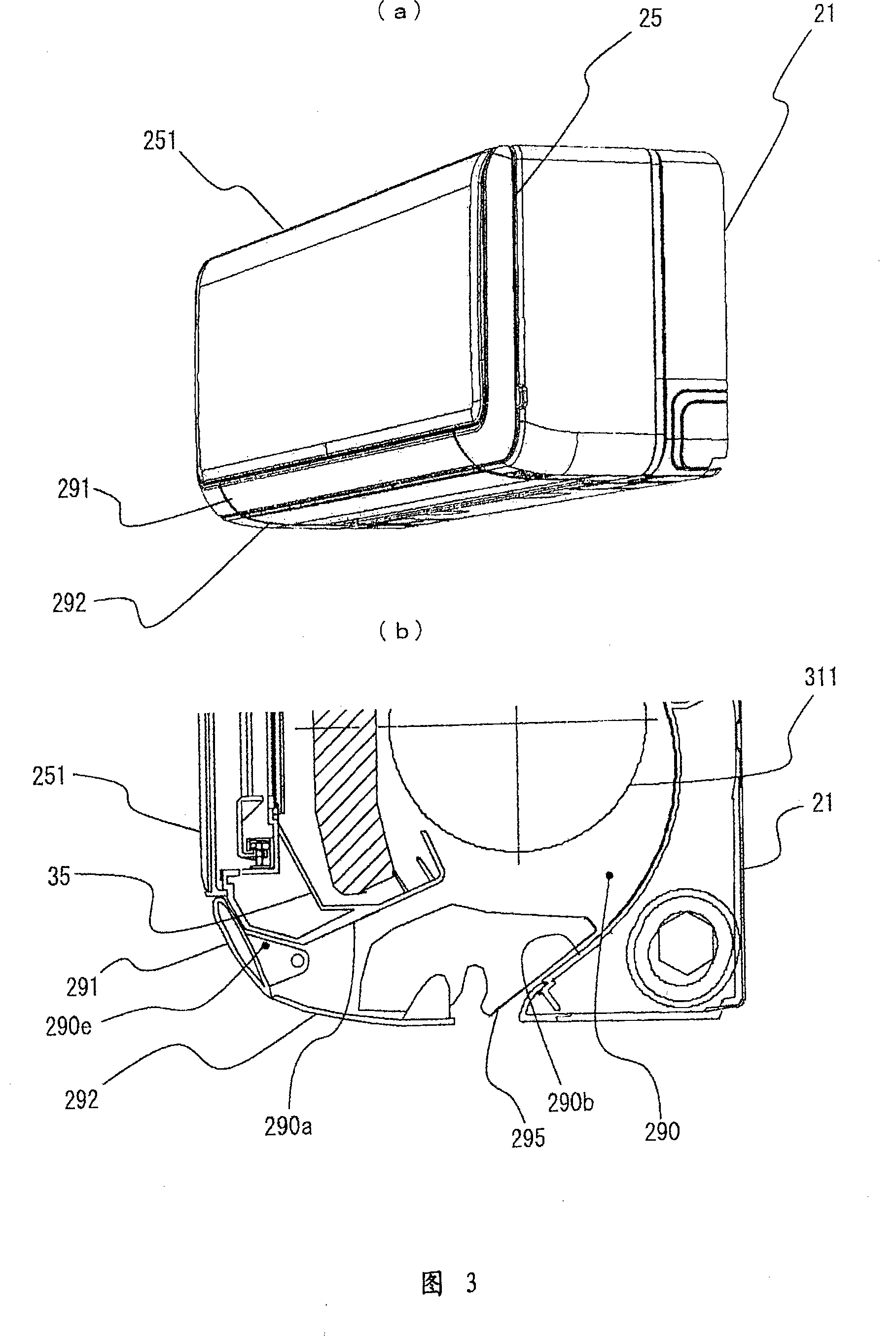
[0039]The air conditioner connects the indoor unit 2 and the outdoor unit 6 with the connecting pipe 8 to perform air conditioning in the room. The indoor unit 2 places an indoor heat exchanger 33 in the central part of the chassis base 21, arranges a blower fan 311 under the heat exchanger 33, installs a dew tray 35, etc., and covers these with a decorative frame 23. A front panel 25 is installed at the front. On the decorative frame 23, an air inlet 27 for sucking in indoor air and an air outlet 29 for blowing out air with adjusted temperature and hu...


PUM


Abstract

The present invention relates to an air conditioner. The air conditioner provided by the invention has the advantage that the exterior projection or concave part hardly exists when not being used and the environment of indoor decoration is not disturbed. Furthermore the direction of blowout air current and the direction of impression which is generated when the upper and lower wind direction boards are seen are same, and no baffle is generated. In the separated wall-type air conditioner which can use a plurality of upper and lower wind direction boards to approximately close the blowing outlet, an enlarging part of the blowing-out air passage which enlarges from the downstream side to the upper part, and an upper wind direction board of the upper and lower wind direction boards which is positioned at the front part of enlarging part and has a central part with convex wind direction surfaces at the surface and back surface and a hollow inner part are provided. The average curvature of wind direction surface which becomes the external surface when the upper wind direction board of the upper and lower wind direction boards is closed is larger than the average curvature of other wind direction surfaces of the upper and lower wind direction boards. The wind direction surface becomes the lower surface when the upper wind direction board of the upper and lower wind direction boards is set in the horizontal direction and furthermore becomes the back surface when the upper wind direction board of the upper and lower wind direction boards is downward.

Description

technical field [0001] The invention relates to an air conditioner, in particular to an air conditioner with improved upper and lower wind direction plates. Background technique [0002] Heat pump air conditioners are widely used as air conditioners, and various attempts have been made to make them more comfortable and easier to use. One of them is the shape of the vertical louvers. [0003] Among heat pump air conditioners, the separate wall-mounted type is widely used because of its harmony with the house, design, and low noise. In this case, since the indoor unit is installed on the upper part of the indoor wall, the up and down louvers are directed downward as much as possible during the heating operation so that the warm air reaches the vicinity of the floor as much as possible; Circulate the cool air widely in the room. [0004] Although heat pump air conditioners are being miniaturized every year, there are also performance problems, and the speed of miniaturizatio...

Claims


Application Information

Patent Timeline
Patent Type & Authority Patents(China)
IPC IPC(8): F24F1/00F24F13/14F24F13/20
Inventor 粟野真和宫崎则夫井本勉时田悟己
Owner HITACHI JOHNSON CONTROLS AIR CONDITIONING INC
Features
  • R&D
  • Intellectual Property
  • Life Sciences
  • Materials
  • Tech Scout
  • Unparalleled Data Quality
  • Higher Quality Content
  • 60% Fewer Hallucinations
Learn More