Illuminating device and control method thereof

A light-emitting device and light-emitting unit technology, applied in the direction of lighting devices, light sources, electric light sources, etc., can solve the problems of cost increase, etc., and achieve the effect of reducing the number of components, low cost, and cost reduction

Active Publication Date: 2009-04-01
PANELSEMI CORP
View PDF0 Cites 10 Cited by
  • Summary
  • Abstract
  • Description
  • Claims
  • Application Information

AI Technical Summary

Problems solved by technology

[0004] However, in the prior art, the photodetector 12 must first detect the luminous intensity of the LED 11 and generate a feedback signal, and then the controller 13 adjusts the brightness of the LED 11 according to the feedback signal.
But along with the increase of the quantity of light-emitting diodes 11, the quantity of controller 13 must also increase thereupon, also cause the increase of cost simultaneously

Method used


Image

  • Illuminating device and control method thereof
  • Illuminating device and control method thereof
  • Illuminating device and control method thereof

Examples


no. 1 example

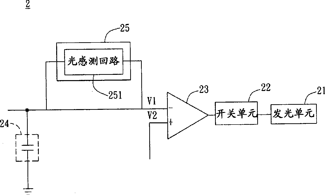
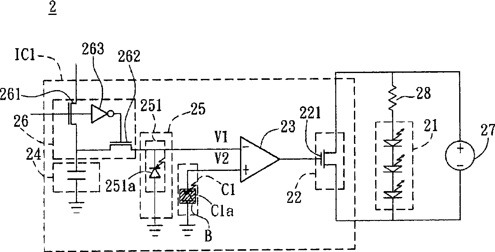
[0073] Please refer to figure 2 As shown, the light emitting device 2 according to the first embodiment of the present invention includes at least one light emitting unit 21 , a switch unit 22 , a comparison unit 23 , a charge storage unit 24 and a sensing unit 25 .

[0074] The light emitting unit 21 can be a cold cathode fluorescent lamp, a hot cathode fluorescent lamp or a light emitting diode. In this embodiment, the light emitting unit 21 is an example of a light emitting diode.

[0075] The switch unit 22 is electrically connected to the light emitting unit 21 . Wherein, the switch unit 22 may include a BiJon Transistor (BJT) or a Metal Oxide Semiconductor Field Effect Transistor (MOSFET). In this embodiment, the switching unit 22 is a MOSFET as an example. Moreover, in this embodiment, the switch unit 22 and the light emitting unit 21 are connected in parallel, but they can also be connected in series or in other ways according to different design methods.

[0076]...

no. 2 example

[0099] Please refer to Figure 7 As shown, the light-emitting device 3 of the second embodiment of the present invention includes a light-emitting unit 31, a switch unit 32, a comparison unit 33, a charge storage unit 34, a sensing unit 35, a control unit 36, and a power supply unit 37. A current limiting unit 38, a rectifying unit 39, a column driving circuit DG1 and a row driving circuit DS1.

[0100] Among them, the switch unit 32, the comparison unit 33, the charge storage unit 34, the sensing unit 35, the control unit 36, the column drive circuit DG1 and the row drive circuit DS1 are the same as the switch unit 22, the comparison unit 23, the charge The structures and functions of the storage unit 24 , the sensing unit 25 , the control unit 26 , the column driving circuit DG, and the row driving circuit DS are the same, so they will not be repeated here.

[0101] It is worth mentioning that at least two of the light emitting unit 31 , the switch unit 32 , the comparison ...

no. 3 example

[0104] Please refer to Figure 8A As shown, the light emitting device 4 of the third embodiment of the present invention includes at least one light emitting unit 41, a switch unit 42, a comparison unit 43, a charge storage unit 44, a sensing unit 45, a control unit 46, a power supply unit 47 and a current limiting unit 48 .

[0105] Among them, the structures and functions of the light-emitting unit 41, the switch unit 42, the comparison unit 43, the charge storage unit 44, the control unit 46, the power supply unit 47 and the current-limiting unit 48 are the same as those of the light-emitting unit 31 and the switch unit of the second embodiment of the present invention. 32. The comparison unit 33, the charge storage unit 34, the control unit 36, the power supply unit 37, and the current limiting unit 38 are the same, so they will not be repeated here.

[0106] The difference between this embodiment and the foregoing embodiments is that the threshold voltage V2 is a preset ...


PUM


Abstract

The invention relates to a light emitting device and a controlling method thereof, wherein, the light emitting device comprises at least one light emitting unit, a switch unit, a comparing element, a charge storage unit and a sensing unit. The switch unit is electrically connected with the light emitting unit and the comparing element respectively; the charge storage unit is electrically connected with the comparing element and stores quantity of electric charge; the sensing unit is electrically connected with the charge storage unit and includes a light sensing circuit which senses light emitting brightness of the light emitting unit, and the sensing unit regulates the quantity of electric charge and the voltage corresponding to the quantity of electric charge according to the light emitting brightness; wherein, the comparing element compares the voltage with a critical voltage and controls the light emitting unit through the switch unit according to the comparative results. The light emitting device and the controlling method thereof can reduce the cost and expense.

Description

technical field [0001] The invention relates to a light emitting device and a control method thereof. Background technique [0002] For liquid crystal display devices such as LCD TVs and computer display screens, if light-emitting diodes are used as the light source of the backlight module, the number of light-emitting diodes required usually ranges from tens to hundreds. Color or a better display image, so controlling the average brightness of LEDs has become one of the very important technologies. Generally, a liquid crystal display device includes a liquid crystal display panel and a backlight module. [0003] Please refer to figure 1 As shown, the conventional backlight module has a plurality of LEDs 11 , a photodetector 12 and a controller 13 . The light detector 12 detects the brightness generated by each LED 11 when each LED 11 emits light, and generates a feedback signal to the controller 13 accordingly, and then the controller 13 adjusts the corresponding light e...

Claims


Application Information

Patent Timeline
Patent Type & Authority Applications(China)
IPC IPC(8): G09G3/34G09G3/36G09G5/10G09G3/20G02F1/133G01J1/42G01J1/44H05B37/02
Inventor 林崇智
Owner PANELSEMI CORP
Why Eureka
Try Eureka