

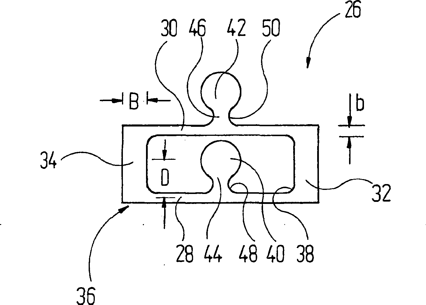
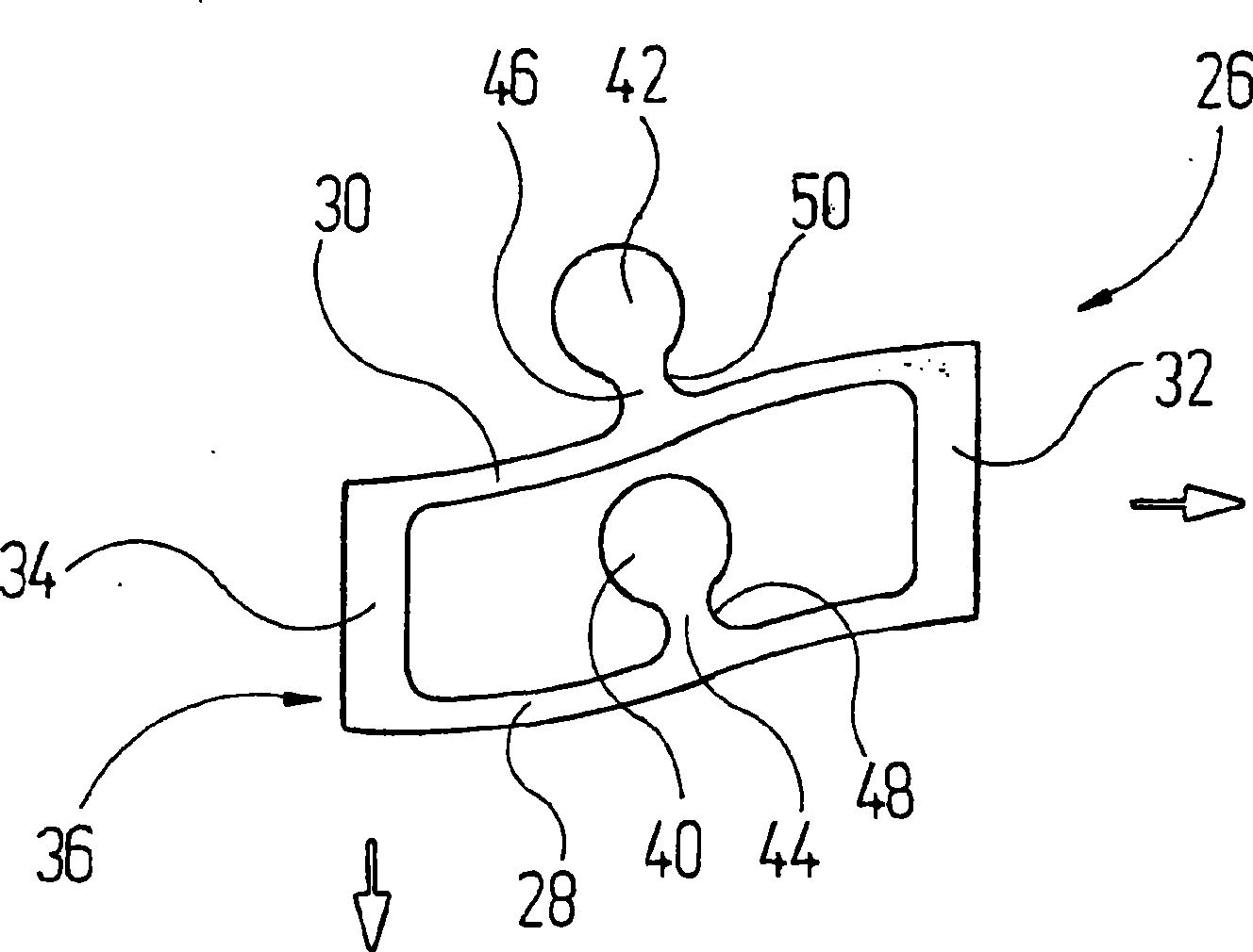
Elastically flexible coupling body
A technology of elastic bending and connecting body, which is applied in the direction of fluid, welding equipment, dental drilling, etc. using vibration, which can solve the problems of broken connecting body and failure of working instruments.
- Summary
- Abstract
- Description
- Claims
- Application Information
AI Technical Summary
Problems solved by technology
Method used
Image

Examples
Embodiment Construction
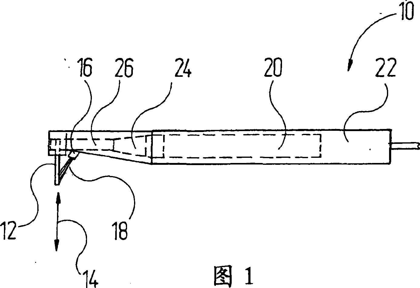
[0050] An ultrasonic handpiece is indicated generally at 10 in FIG. 1 and is used to drive a tool 12 .
[0051] The tool 12 can be, for example, a lancet-shaped flat tool with which the sides of the tooth can be treated. The tool 12 is moved in the direction of the arrow 14 shown in the figure. During work with the tool 12 , a jet of working fluid 18 , which contains grinding media suspended in water, is sprayed onto the tool via a nozzle 16 .
[0052]A sonotrode 20 installed inside the handle 22 of the handpiece 10 is used to generate the vertical reciprocating movement of the tool 12 in FIG. 1 with an amplitude of several tens to several hundreds of μm. The sonotrode 20 comprises a plurality of piezoelectric plates stacked one behind the other in the axial direction and is connected to an ultrasonic vibration unit 24 at its output end located on the left in FIG. 1 . The ultrasonic vibration unit is used to concentrate the ultrasonic energy through the "funnel effect" and p...
PUM
 Abstract
Description
Claims
Application Information