A region coated end cap group for suppressing mode instability and application thereof

An end cap and area technology, applied in the field of fiber laser, can solve the problems of loss of high-order modes and suppression mode instability, and achieve the effect of suppressing the generation of high-order modes and suppressing mode instability

Pending Publication Date: 2019-01-18
NAT UNIV OF DEFENSE TECH
View PDF5 Cites 4 Cited by
  • Summary
  • Abstract
  • Description
  • Claims
  • Application Information

AI Technical Summary

Problems solved by technology

[0005] For the above-mentioned existing technologies, the mode instability effect is suppressed by using a gain fiber that supports few fiber modes, using a pump source corresponding to a low absorption coefficient of the gain fiber, and increasing the bending loss of the fiber to reduce the mode instability effect. The oscillation of high-order modes cannot be substantially reduced. With the increase of output power, the mode instability effect will still appear. At the same time, the fundamental mode oscillation is effectively improved, and a large amount of high-order modes are lost, thereby suppressing the mode instability effect of the fiber laser oscillator

Method used


Image

  • A region coated end cap group for suppressing mode instability and application thereof
  • A region coated end cap group for suppressing mode instability and application thereof
  • A region coated end cap group for suppressing mode instability and application thereof

Examples


Embodiment 1

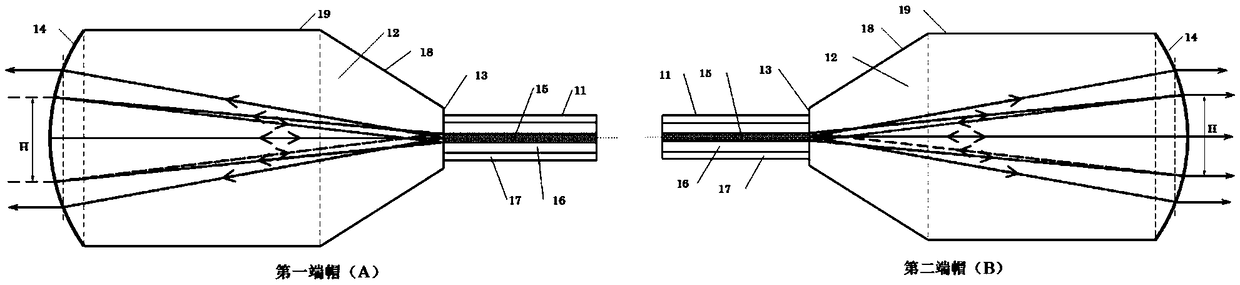
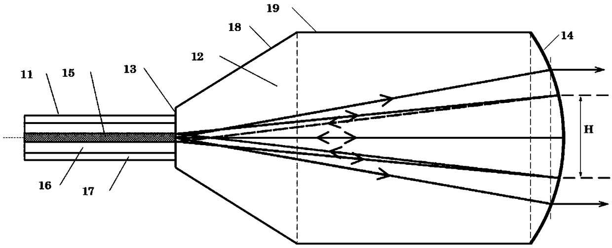
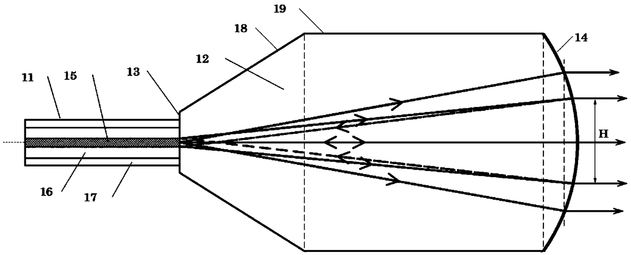
[0025] A regional coating end cap group with unstable suppression mode, the structure diagram is as follows figure 1 As shown, including the first end cap A and the second end cap B, the first end cap A and the second end cap B both include the following structures, respectively as figure 2 with 3Shown: optical fiber 11, specially designed quartz block 12: the optical fiber 11 can be a double-clad optical fiber consisting of a core 15, an inner cladding 16 and an outer cladding 17, or a single-clad optical fiber consisting of a core 15 , cladding 17; Quartz block 12 is an integral structure formed by successively connecting circular frustum 18, cylinder 19 and output curved surface body 14 with the same size of the connecting end face; The smaller end face of 18) becomes an interface 13 after welding; after the laser is transmitted from the fiber core 15 to the interface 13, it enters the quartz block 12, and after the laser beam passes through the area of ​​the round table ...

Embodiment 2

[0027] A regional coating end cap group with unstable suppression mode, its structure is basically the same as that of Embodiment 1, the difference is that the spatial region corresponding to the base mode on the curved surface of the output curved surface body 14 in the first end cap A is coated with a high reflection film, and the specific reflectivity The value is 100%, no transmitted light, the area outside the fundamental mode is coated with an anti-reflection coating, the transmittance is 100%, and the laser light is completely transmitted; the output surface body 14 in the second end cap B is coated with a 10% reflective film on the corresponding space area of ​​the fundamental mode, 90 % antireflection coating, the area outside the base mode is coated with antireflection coating, the transmittance is 100%, and the laser light is completely transmitted.

Embodiment 3

[0029] An all-fiber oscillator using a wavelength-coated end cap group that suppresses stimulated Raman scattering, its structure is as follows Figure 4 As shown, it includes a first end cap A, a second end cap B, a rare earth particle-doped gain fiber 23, a pump signal beam combiner 24, a fiber-coupled semiconductor laser 25, a signal energy transmission fiber 26, and a pump energy transmission fiber 27 The signal energy transmission fiber 26 connects the first end cap A, the pump signal combiner 24, the rare earth particle gain fiber 23 and the second end cap B sequentially; the pump signal combiner 24 has one or A plurality of pumping arms, a signal input arm, and a signal output arm; a group of fiber-coupled semiconductor lasers 25 are connected to the pumping arm of the pumping signal beam combiner 24 through the pumping energy transmission fiber 27; the first end cap The structures of A and the second end cap B are as shown in Example 1, and the dimensions of the compon...


PUM


Abstract

A region coated end cap group for suppressing mode instability comprises a first end cap and a second end cap, the two end caps comprising an optical fiber and a quartz block; The quartz block is formed by connecting a circular table, and the cylinder and the output curved surface in turn to form an integral structure, wherein the circular table, the cylinder and the output curved surface has thesame connecting end face. One end face of the optical fiber is welded with the smaller end face of the circular table to form an interface; The extension line of the core line of the optical fiber isthe center line of the circular table, the cylinder and the output curved surface; The surface of the output curved surface is centered on the intersection point of the core extension line and the interface of the optical fiber, Taking the sum of the lengths of the quartz block centerline in the circular table, the cylinder and the output curved surface as the radius of curvature, the different regions of the output curved surface have different coatings, the space region of the fundamental mode on the first end cap curved surface is a high reflectivity film, and the region outside the fundamental mode is a full transmission film; The space region of the fundamental mode on the curved surface of the second end cap is a low-reflectivity film, and the region other than the fundamental mode is a full-transmission film. The invention can suppress the mode instability effect in the all-optical fiber oscillator.

Description

technical field [0001] The invention generally relates to the field of fiber lasers, in particular to an end cap group for suppressing mode instability and its application. Background technique [0002] High-power fiber lasers are widely used in laser cutting, laser cladding, 3D printing and other fields. In recent years, with the double-clad fiber manufacturing process and the power increase of high-brightness semiconductor lasers, the output power of single-channel high-power fiber laser has been developed rapidly, from 100 watts at the beginning of the 21st century to the current 10 kilowatts. With the continuous improvement of fiber laser output power, the mode instability effect has become the main factor limiting the increase of high-power fiber laser output power. The way to suppress mode instability in traditional fiber lasers is to increase the bending loss of the gain fiber and select the wavelength of the pump source corresponding to the low absorption coefficien...

Claims


Application Information

Patent Timeline
Patent Type & Authority Applications(China)
IPC IPC(8): H01S3/08
CPCH01S3/08013H01S3/08018
Inventor 叶云王小林许晓军史尘奚小明张汉伟陈子伦王泽锋
Owner NAT UNIV OF DEFENSE TECH
Why Eureka
Try Eureka