Efficient heat dissipation structure for solar inverter

A technology of heat dissipation structure and inverter, which is applied in the direction of transforming equipment structural parts, cleaning methods and utensils, chemical instruments and methods, etc. Efficient, easy to shake off effect

Inactive Publication Date: 2020-12-04
泉州泉港博洋机械设计有限公司
View PDF9 Cites 1 Cited by
  • Summary
  • Abstract
  • Description
  • Claims
  • Application Information

AI Technical Summary

Problems solved by technology

[0003] During the actual use of solar inverters with high-efficiency heat dissipation structures, a large amount of impurities and dust are easily attached to the fins during the heat dissipation process in the heat dissipation structure, which reduces the heat conduction effect of the fins, and manual cleaning needs to be done to them Dismantling is more labor-intensive

Method used


Image

  • Efficient heat dissipation structure for solar inverter
  • Efficient heat dissipation structure for solar inverter
  • Efficient heat dissipation structure for solar inverter

Examples


Embodiment 1

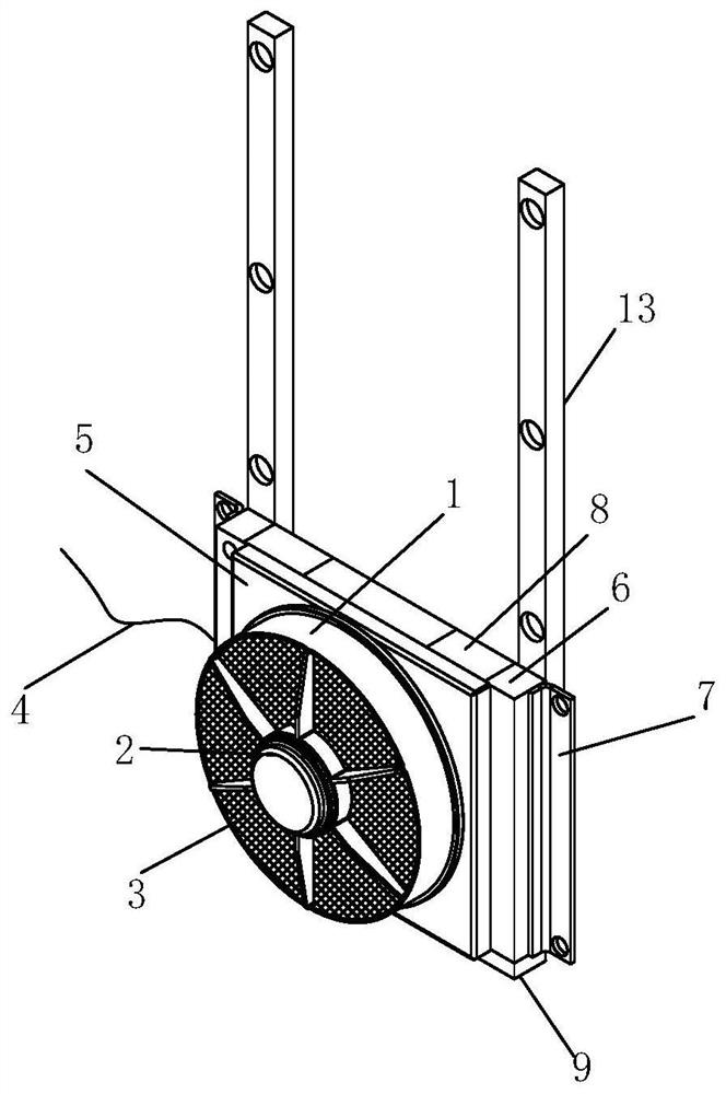
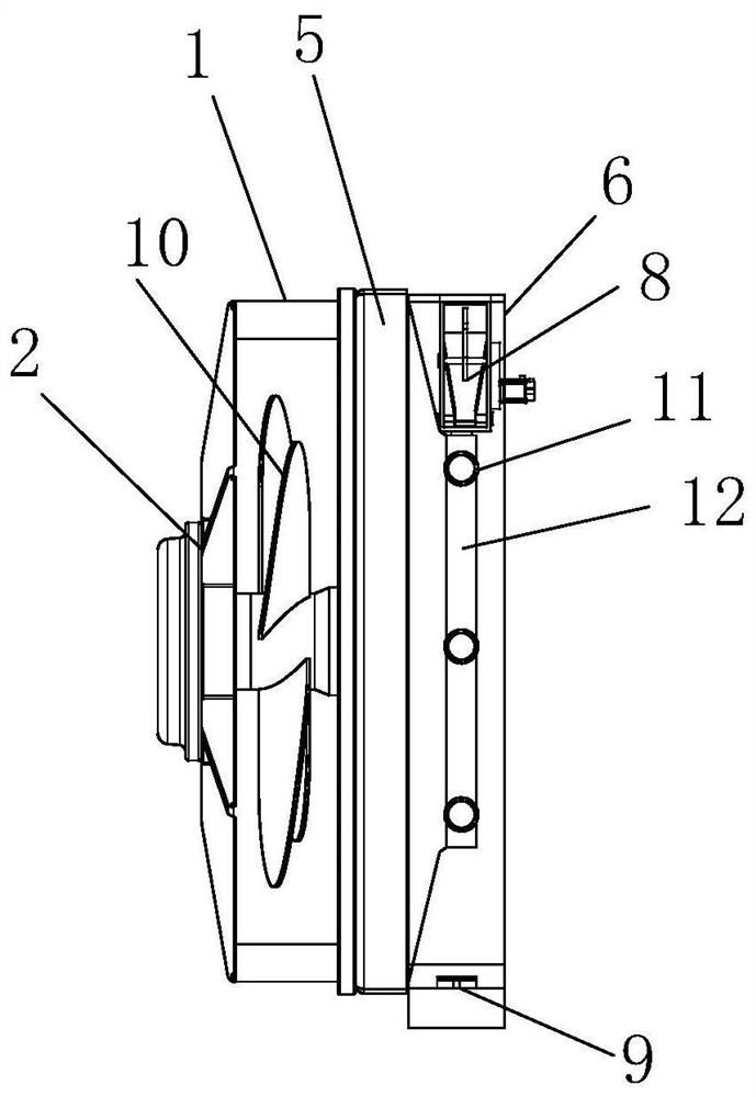
[0029] see figure 1 and figure 2 , the present invention provides a high-efficiency heat dissipation structure for solar inverters through improvement, including a fixed cover 1, a stabilizer 2 is fixed on the front surface of the fixed cover 1, a spacer 3 is embedded inside the stabilizer 2, and the left lower end of the fixed cover 1 The power line 4 is installed, the back of the fixed cover 1 is fixed to the back plate 5, the back of the back plate 5 is connected to the fixed box 6, the left and right sides of the fixed box 6 are welded with the mounting parts 7, and the fan 10 is arranged in the middle of the fixed cover 1 , and the fan 10 is electrically connected to the power line 4, the left and right sides of the fixed box 6 are fixed by springs 11 and fins 12, the back of the fixed box 6 is welded with a mounting rod 13 near the outer edge, and the left and right ends of the top of the fixed box 6 are fixed. There is a cleaning device 8, and the bottom of the fixed ...

Embodiment 2

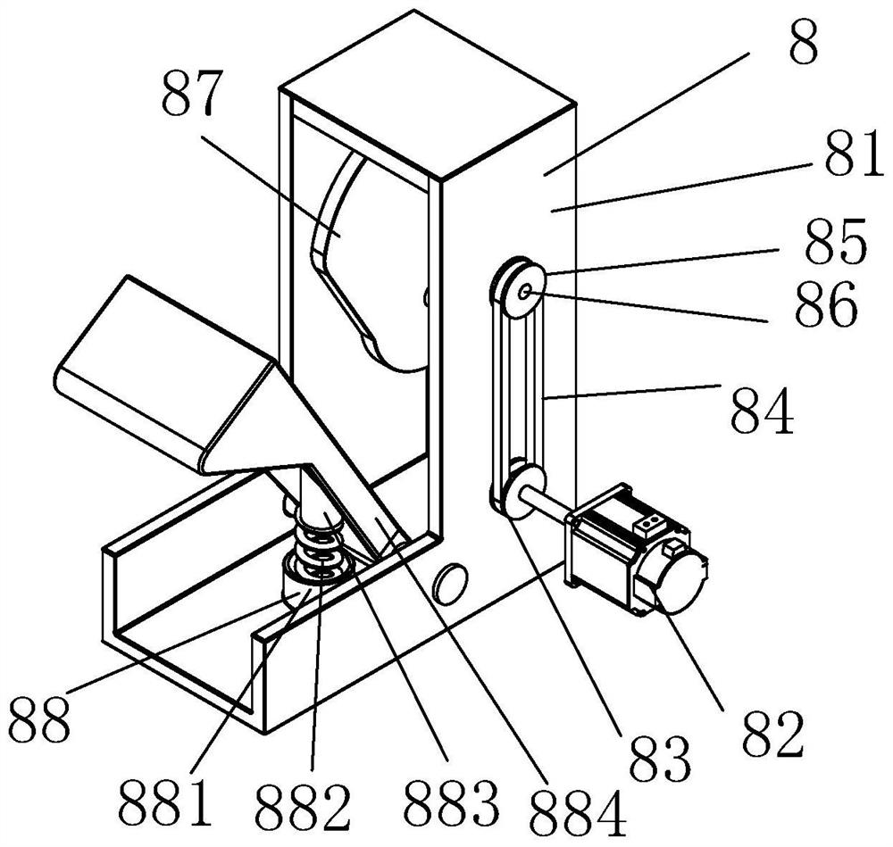
[0034]The present invention provides a high-efficiency heat dissipation structure for solar inverters through improvement. There are six groups of springs 11, and three groups are installed on both sides of the fixed box 6, effectively making the fins 12 assist in the heat dissipation under the condition of force. Shaking; the distance between the top of the toggle block 87 and the inner top of the housing 81 is 3cm to prevent collision with the housing 81 during the rotation of the toggle block 87; the top of the fixed plate 91 is bonded with a layer of 2mm thick Silicone layer to prevent leakage during collection.

[0035] The present invention provides a high-efficiency heat dissipation structure for a solar inverter through improvement, and its working principle is as follows;

[0036] First, when the heat dissipation structure needs to be used, first install the heat dissipation structure to the position where it needs to be used, then connect the power line 4 to the cont...


PUM


Abstract

The invention discloses an efficient heat dissipation structure for a solar inverter. The efficient heat dissipation structure comprises a fixing cover, a stabilizing piece, a cleaning device and a collecting mechanism, wherein the cleaning device is installed at the upper end of the inner side of a fixing box, and after a mechanism in the cleaning device conducts transmission, fins at the bottompart can be knocked back and forth, so that dust attached to the surface of the fins falls off, thus manual cleaning work is reduced, convenience and rapidness are achieved, and the working efficiencyis improved; under the driving of an independent motor in the cleaning device, a shifting block is driven by a belt wheel to press down the impacting mechanism in a reciprocating manner, a knocking piece mounted in the impacting mechanism can continuously impact the top parts of the fins, and effective shock excitation is carried out in cooperation with springs at the two ends of the side faces of the fins, so that dust and impurities are shaken off conveniently; and the collecting mechanism is arranged at the bottom part of the fixing box, can collect dust falling from the fins, is connectedwith the fixing box in a buckling mode, and is convenient and rapid to disassemble and assemble.

Description

technical field [0001] The invention relates to the related field of solar inverter accessories, in particular to a high-efficiency heat dissipation structure for a solar inverter. Background technique [0002] Inverters, also known as power regulators and power regulators, are an essential part of photovoltaic systems. The main function of photovoltaic inverters is to convert the direct current generated by solar panels into alternating current for household appliances. All the generated electricity must be processed by the inverter before it can be exported to the outside world. A heat dissipation structure must be installed in the solar inverter to efficiently dissipate heat for its work. [0003] In the actual use of solar inverters with high-efficiency heat dissipation structures, a large amount of impurities and dust are easily attached to the fins during the heat dissipation process in the heat dissipation structure, which reduces the heat conduction effect of the fin...

Claims


Application Information

Patent Timeline
Patent Type & Authority Applications(China)
IPC IPC(8): H02S40/32H02M7/00H05K7/20B08B7/02
CPCB08B7/02H02M7/003H05K7/209H05K7/20909H02S40/32Y02E10/50
Inventor 邓庆华
Owner 泉州泉港博洋机械设计有限公司
Why Eureka
Try Eureka