Resin-made cage and bearing
A resin-made cage technology, applied to shafts and bearings, bearings, ball bearings, etc., to achieve the effect of improving production efficiency
- Summary
- Abstract
- Description
- Claims
- Application Information
AI Technical Summary
Problems solved by technology
Method used
Image

Examples
Embodiment 1
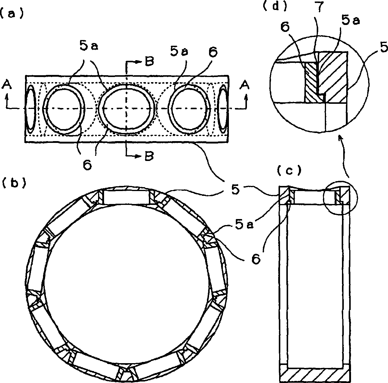
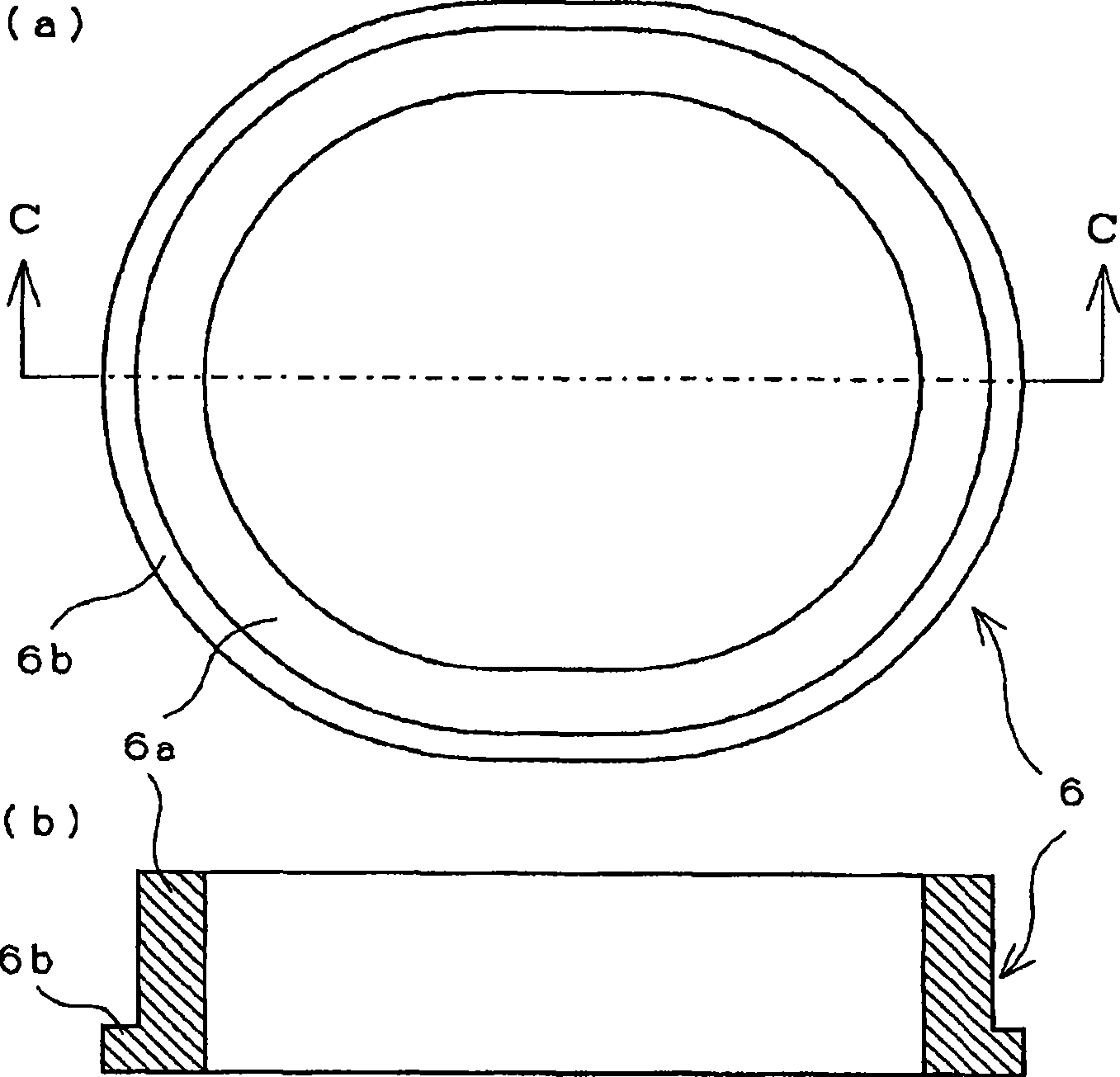
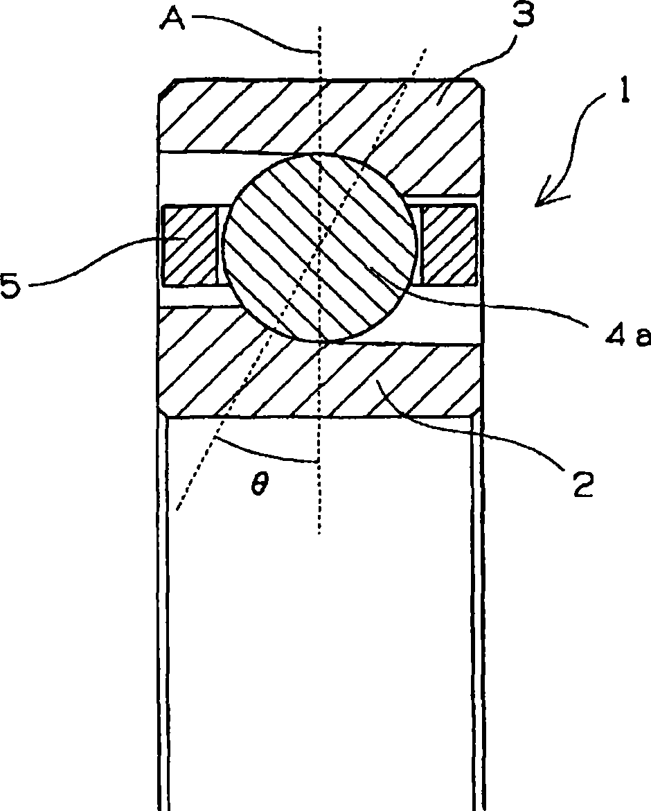
[0072] figure 1 It is a group diagram (part of a cross-sectional view) showing a resin-made cage. figure 1 (a) represents a plan view, figure 1 (b) means figure 1 (a) Front view of section A-A, figure 1 (c) means figure 1 (a) side view of the B-B section, figure 1 (d) indicates figure 1 (c) Enlarged view of the circle-marked portion. like figure 1 (a)~ figure 1 As shown in (d), the resin cage 5 has a plurality of pockets 5a penetrating in the radial direction in the annular member, and pockets for accommodating rolling elements are attached to the pockets 5a from the inner ring side. Component 6. like figure 1 As shown in (d), a structure in which the pocket member 6 is bonded to the pocket portion 5a via the adhesive layer 7 is formed. For the pocket member 6, an enlarged view is shown in figure 2 .
[0073] The resin-made retainer 5 main body is a molded body of the first resin composition containing PEEK and PTFE.
[0074] The method of mixing and ...
PUM
| Property | Measurement | Unit |
|---|---|---|
| tensile strength | aaaaa | aaaaa |
| tensile strength | aaaaa | aaaaa |
| tensile strength | aaaaa | aaaaa |
Abstract
Description
Claims
Application Information
 - Generate Ideas
- Intellectual Property
- Life Sciences
- Materials
- Tech Scout
- Unparalleled Data Quality
- Higher Quality Content
- 60% Fewer Hallucinations
Browse by: Latest US Patents, China's latest patents, Technical Efficacy Thesaurus, Application Domain, Technology Topic, Popular Technical Reports.
© 2025 PatSnap. All rights reserved.Legal|Privacy policy|Modern Slavery Act Transparency Statement|Sitemap|About US| Contact US: help@patsnap.com