
Pulse shaping circuit for crystal oscillator

A technology of crystal oscillator and pulse shaping, applied in the direction of pulse processing, pulse technology, electrical components, etc., can solve the problem of not providing the influence of crystal oscillator

Inactive Publication Date: 2009-04-01
NXP BV
View PDF0 Cites 3 Cited by
  • Summary
  • Abstract
  • Description
  • Claims
  • Application Information

AI Technical Summary

Problems solved by technology

However, in many cases, no solution has been provided for addressing the problem of the impact of harsh environments on crystal oscillators

Method used


Image

  • Pulse shaping circuit for crystal oscillator
  • Pulse shaping circuit for crystal oscillator
  • Pulse shaping circuit for crystal oscillator

Examples


Embodiment Construction

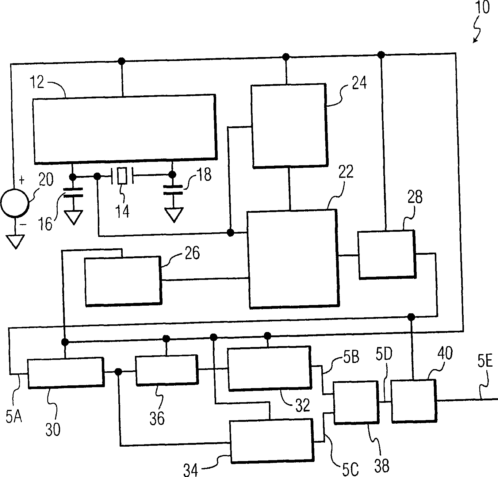
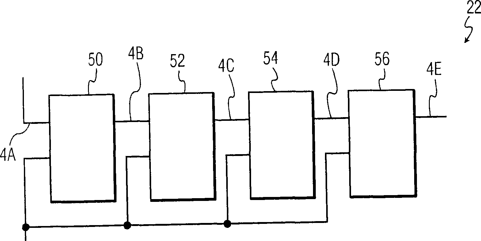
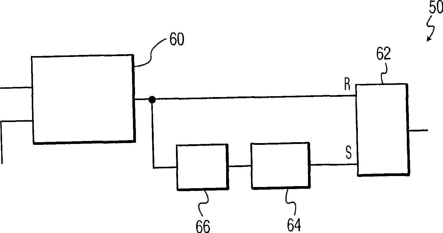
[0020] According to an embodiment of the present invention, a signal output by a crystal oscillator circuit is pulse shaped using a variable threshold multi-stage pulse shaping circuit. Each stage of the pulse shaping circuit includes a Schmitt trigger that drives the latch input, and the Schmitt trigger has a programmable trigger point that can be controlled to suppress distorted pulses generated by the crystal oscillator circuit . Thus, pulse shaping circuits can be used to smooth out narrow pulses at the output of a crystal oscillator before it is distributed to other circuits.

[0021] For example, a variable-threshold multi-stage pulse shaping circuit as described herein can be used to generate clock signals for electronic circuits that are more resistant to noise and other environmental influences, thereby reducing the risk of clock-related errors in electronic circuits. possibility. In other cases, pulse shaped signals may be used in other applications where a stable ...


PUM


Abstract

A circuit arrangement and method utilize a variable threshold, multi-stage pulse shaping circuit to pulse shape a signal output by a crystal oscillator circuit. Each stage of the pulse shaping circuit includes a Schmitt trigger that drives an input of a latch, and that has a programmable trip point controlled to reject distorted pulses generated by the crystal oscillator circuit. A variable threshold, multi-stage pulse shaping circuit may be used, for example, to generate a clock signal for an electronic circuit that is more resistant to noise and other environmental effects, thereby reducing the likelihood of clock-related errors in the electronic circuit.

Description

technical field [0001] The present invention generally relates to a method and a circuit arrangement for generating a clock signal using a crystal oscillator. Background technique [0002] Crystal oscillators are used to generate electrical signals with very precise frequencies. Electrical signals produced by crystal oscillator circuits are used in many applications that require a precise time reference, such as keeping track of time in watches, to provide a stable clock signal for digital integrated circuits and to stabilize the frequency of radio transmitters. [0003] Especially when a crystal oscillator circuit is used to generate a clock signal for a digital integrated circuit, special care must be taken to ensure that the clock signal is stable and accurate, as distortion or irregularities in such a clock signal can lead to indeterminate results and / or data corruption. [0004] Crystal oscillator circuits are generally designed as circuits where it is desirable to ...

Claims


Application Information

Patent Timeline
IPC IPC(8): H03K5/1252
CPCH03K5/1252H03K5/082
Inventor 凯文·马胡提
Owner NXP BV
Learn More