
Controller of injection molding machine

A technology for injection molding machines and control devices, which is applied in the field of control devices for injection molding machines, and can solve problems such as troublesome adjustment and setting operations

Active Publication Date: 2009-04-08
NISSEI PLASTIC IND CO LTD
View PDF1 Cites 27 Cited by
  • Summary
  • Abstract
  • Description
  • Claims
  • Application Information

AI Technical Summary

Problems solved by technology

Therefore, in order to ensure accuracy (accuracy), it is necessary to adjust or set the control system in consideration of such time shifts and errors, and the adjustment and setting operations become troublesome.

Method used


Image

  • Controller of injection molding machine
  • Controller of injection molding machine
  • Controller of injection molding machine

Examples


Embodiment Construction

[0023] Hereinafter, the preferred embodiments of the present invention will be cited and described in detail based on the drawings. Among them, the drawings are not used to specify the present invention, but to facilitate the understanding of the present invention. In addition, for the well-known parts, in order to avoid unclearness of the present invention, detailed descriptions are omitted.

[0024] First, with reference to FIG. 4, the schematic structure of the injection molding machine M provided with the control apparatus 1 in this Example is demonstrated.

[0025] In Figure 4, M is an injection molding machine, including an injection device Mi and a mold fastening device. The illustration of the mold fastening device is omitted, and only the die C supported by the mold fastening device is shown. The injection device Mi is equipped with a heating cylinder 11 with an injection nozzle 11n at the front end and a funnel 21 at the rear. A screw 22 is inserted into the heating cyli...


PUM


Abstract

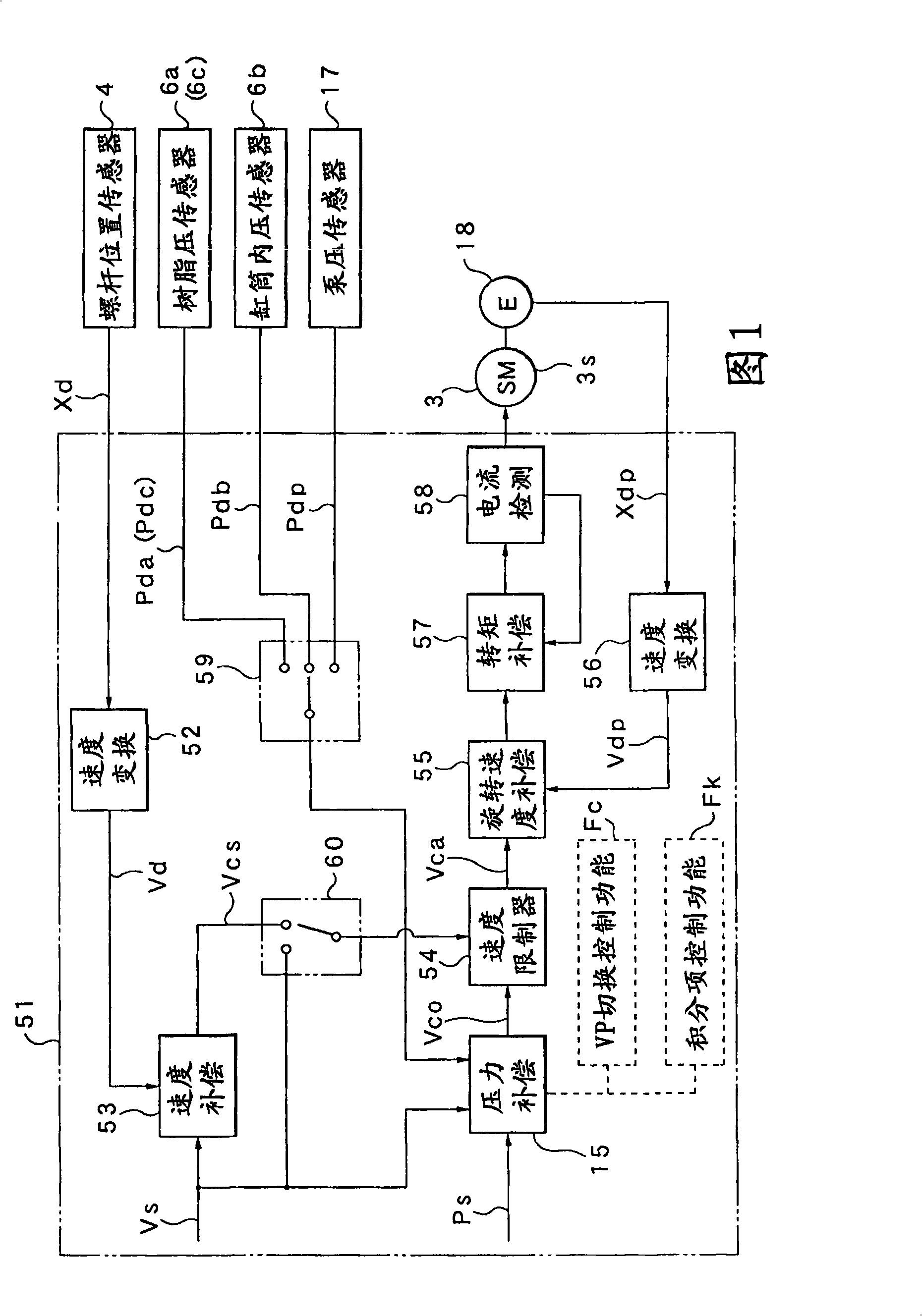
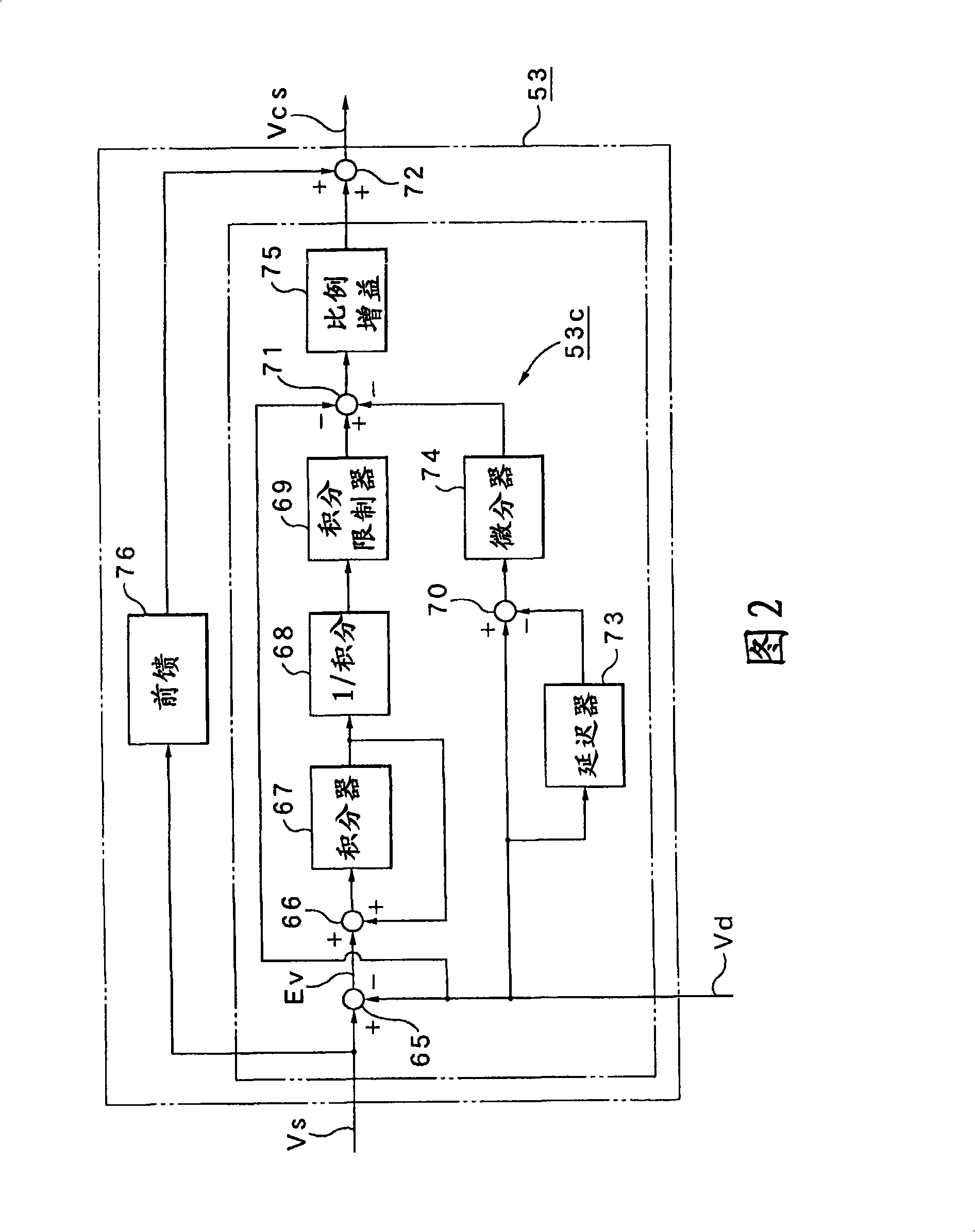
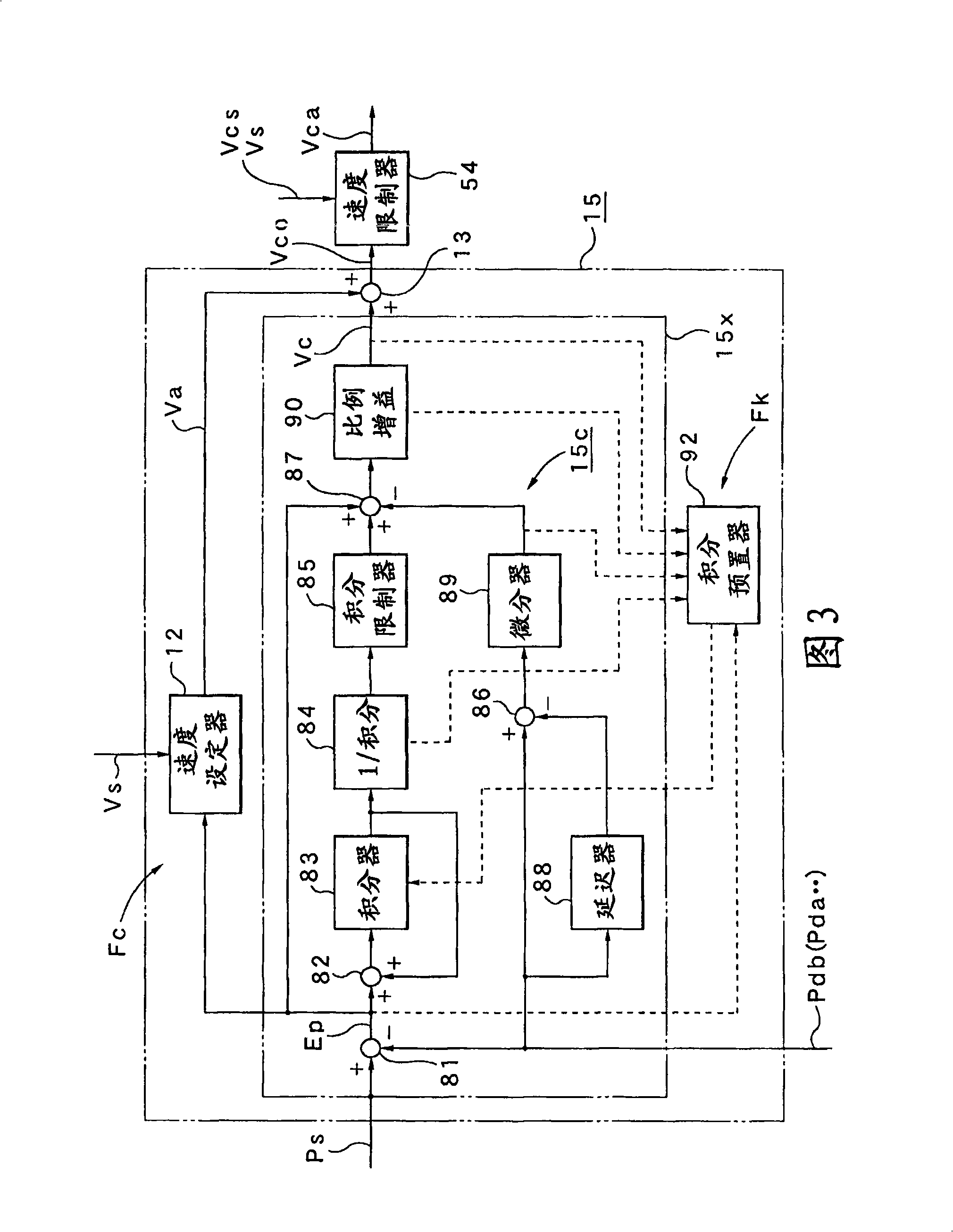
The present invention discloses a control device of an injection molding machine, which comprises a speed feedback control system for carrying out speed feedback control on the basis of a speed detected value Vd obtained by converting a position detected value Xd obtained from a screw position sensor 4, a pressure feedback control system for carrying out a pressure feedback control on the basis of a pressure detected value Pdb obtained from an injection pressure sensor 6b, and a VP switching control function portion Fc for carrying out switching from a speed control region to a pressure control region Zp when a pressure deviation Ep between a preset pressure set value Ps and the pressure detected value Pdb becomes a preset switching determination value Eps or less and carrying out the switching to the pressure control region Zp after control of a speed command value in the speed control region Zv by a predetermined control pattern Dp at this switching.

Description

Technical field [0001] The present invention relates to a control device for an injection molding machine. The control device controls each operation process in a molding cycle by variably controlling the rotation speed of a drive motor in a hydraulic pump. Background technique [0002] Conventionally, as an injection molding machine equipped with a control device that controls each operation step in the molding cycle by variably controlling the rotation speed of a drive motor in a hydraulic pump, there is known Japanese Patent Publication No. 2007- The injection molding machine described in 69500. [0003] In this injection molding machine, a variable discharge hydraulic pump capable of setting a fixed discharge flow rate by changing the angle of the swash plate is used, and a control unit is installed that switches the hydraulic pump to and according to predetermined conditions. The fixed discharge flow rate corresponding to each operation process is set, and the rotation speed...

Claims


Application Information

Patent Timeline
Patent Type & Authority Applications(China)
IPC IPC(8): B29C45/76
CPCB29C2945/76006B29C2945/76665B29C2945/76882B29C2045/776B29C2945/76214B29C2945/76287B29C2945/76381B29C2945/7611B29C2945/76969B29C2945/76187B29C2945/76595B29C2945/76083B29C45/77B29C2945/76498B29C2945/76307
Inventor 箱田隆驹村勇加藤利美中村清
Owner NISSEI PLASTIC IND CO LTD
Learn More