
Dust collecting and processing system in textile machine

A treatment system and mechanical technology, applied in the field of cotton collection treatment system, can solve the problems of increasing the size of the blower, increasing the energy consumption, and increasing the size of the machine, so as to reduce the cross-sectional area, reduce the pressure loss, reduce the The effect of machine size

Active Publication Date: 2009-04-08
MURATA MASCH LTD
View PDF3 Cites 9 Cited by
  • Summary
  • Abstract
  • Description
  • Claims
  • Application Information

AI Technical Summary

Problems solved by technology

(2) Due to the structure that maintains static pressure through a long channel, the pressure loss becomes larger
Therefore, the cross-sectional dimension d1 of the channel must be increased, resulting in an increase in the size of the machine
(3) In order to compensate for the static pressure fluctuation and pressure loss of (1) and (2) above, the size of the blower must be increased, resulting in an increase in energy consumption
(4) In the collecting room, there are operating parts such as bypass switching, and flying flowers after collecting are easy to gather in the operating part

Method used


Image

  • Dust collecting and processing system in textile machine
  • Dust collecting and processing system in textile machine
  • Dust collecting and processing system in textile machine

Examples


Embodiment Construction

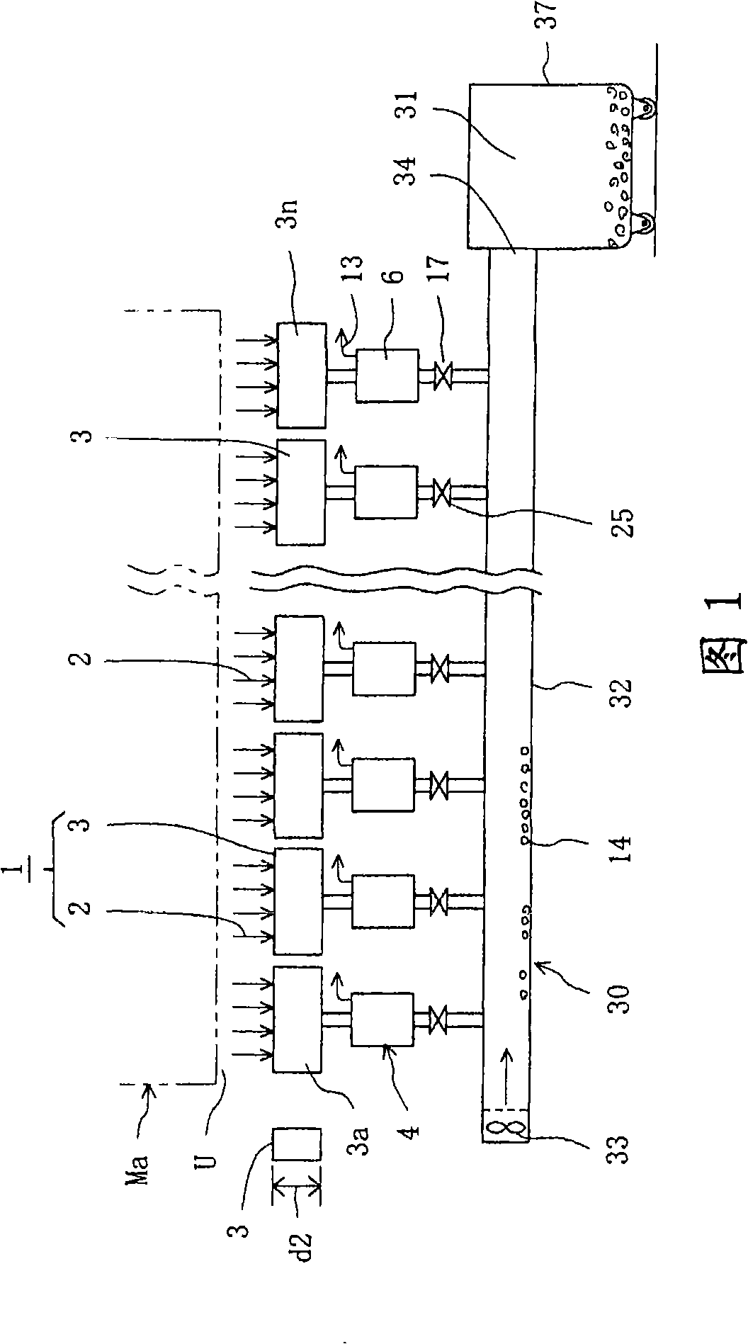
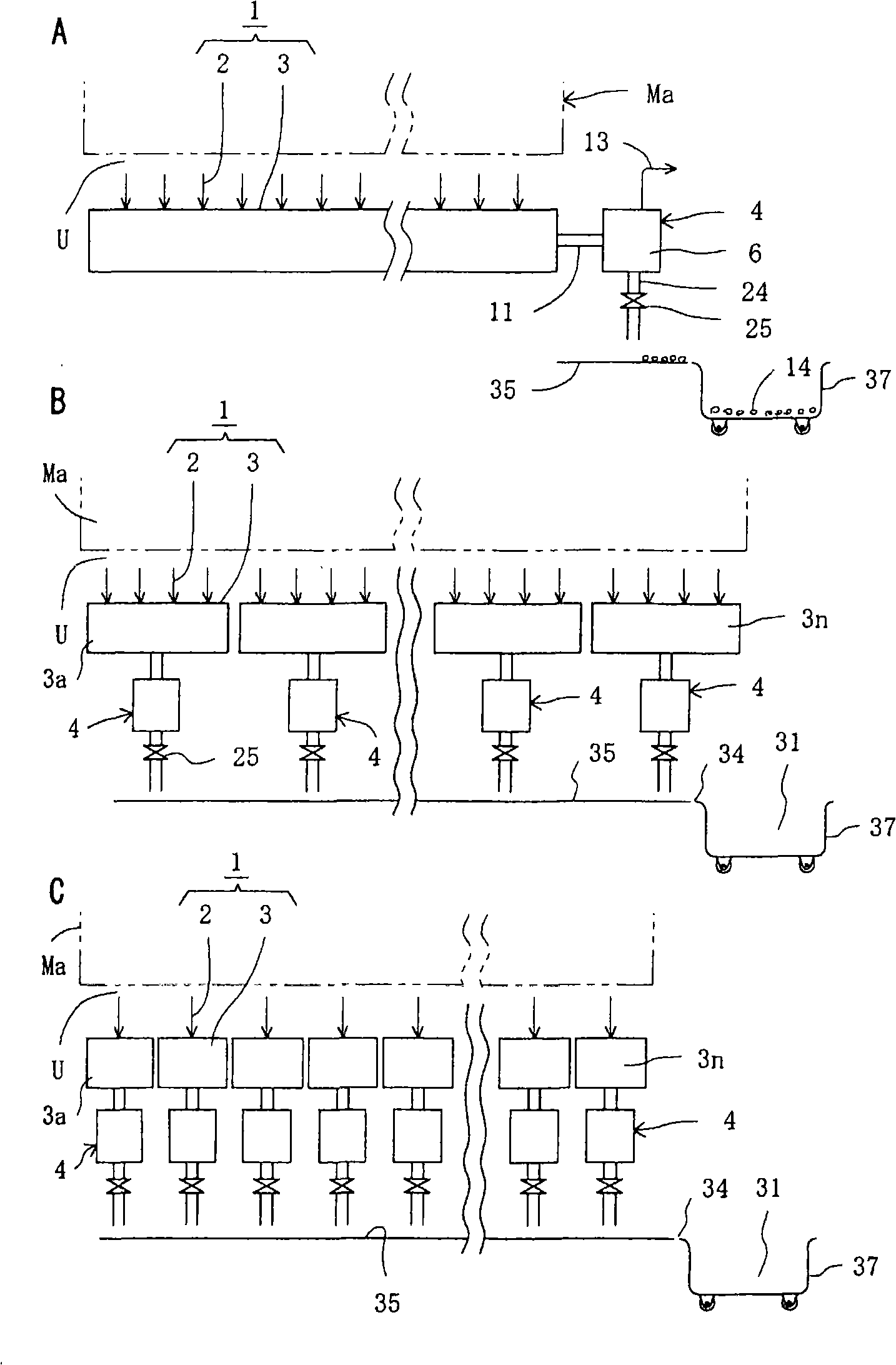
[0026] Hereinafter, the cotton collection processing system in the textile machine according to an embodiment of the present invention will be described with reference to the drawings.

[0027] First, regarding an example of a textile machine using the cotton collection processing system according to an embodiment of the present invention, according to FIGS. 6 to Figure 8 The illustrated textile machine M will be described. The spinning machine M has a structure in which a plurality of spinning units U (hereinafter referred to as spindles U) are arranged in one direction on one machine table Ma. In the spinning machine M, first, the sliver L is sent to the drafting device D, and the spun yarn Y is formed by the spinning section Sp. Then, the spun yarn Y passes through the grip roller Rn, the thick yarn remover Z, and the like, and is wound around the winding section W to form a package PW. In the figure, P is the splicing cart for splicing. The splicing trolley P moves along the l...


PUM


Abstract

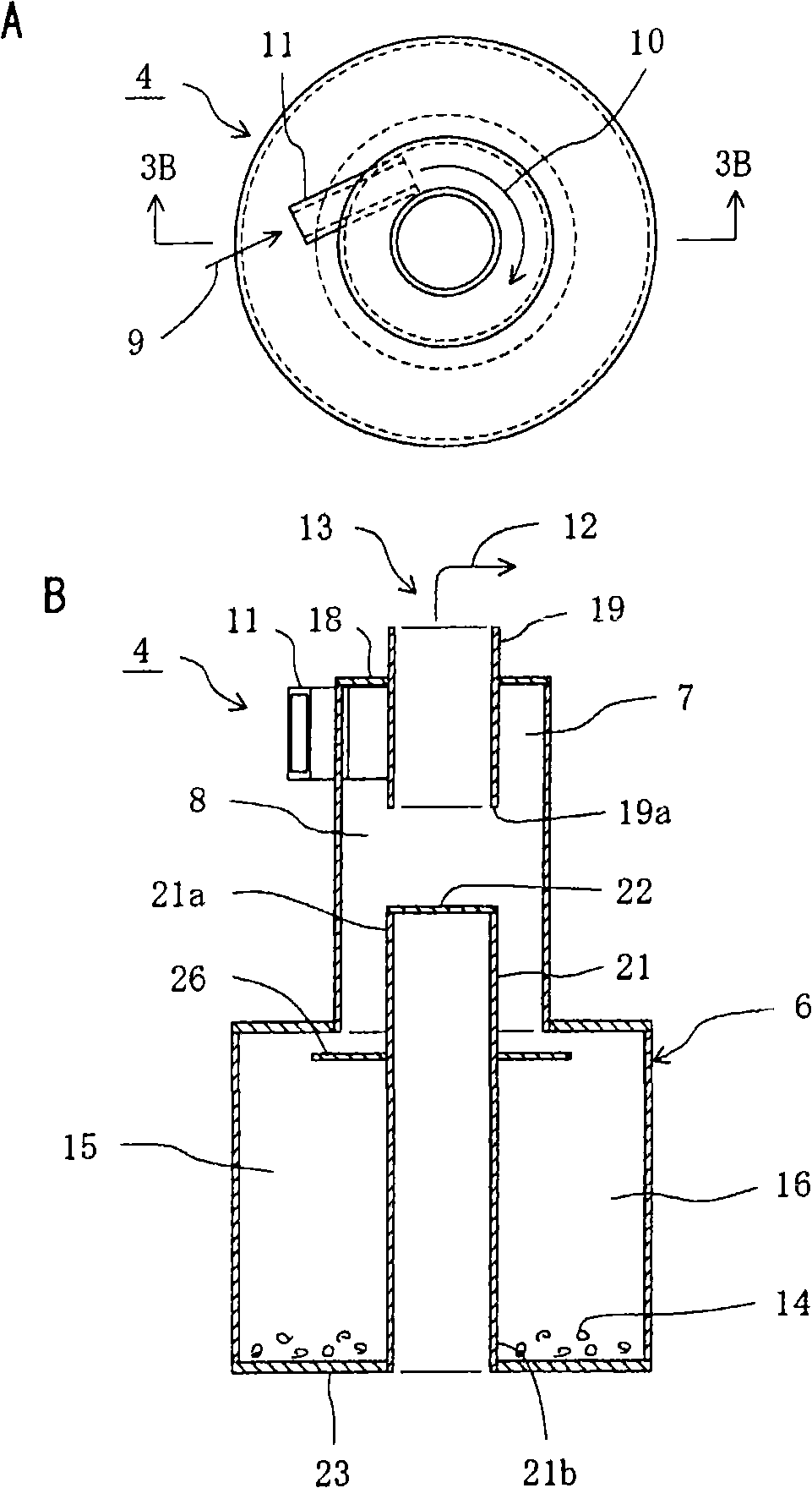
The present invention provides a dust collecting and processing system that sucks and collects fly waste generated during operation of a spinning machine or the like. In the dust collecting and processing system, a centrifugal separator is applied to a fly waste sucking section to prevent a possible variation in suction force and to reduce a machine frame size and power consumption. The dust collecting and processing system includes a large number of units (U) arranged in a machine frame (Ma) in one direction and each including a fly waste suction line (1) that sucks fly waste or the like, and a fly waste separating means (4) for separating the fly waste from suction air. The dust collecting and processing system sucks the fly waste generated during operation of each of the units (U) for separating and collecting the fly waste or like. The fly waste separating means (4) is provided for the fly waste suction line (1) in association with at least one unit (U). The fly waste separating means (4) includes a centrifugal separator (6). The centrifugal separator (6) separates and sucks the fly waste so that the separated fly waste is collected in a dust collecting section (31) via a fly waste conveying means (4).

Description

Technical field [0001] The present invention relates to a collection and processing system for collecting and processing fly, dust, etc. generated during operation in various fiber machines such as textile machines and winders. Background technique [0002] Conventionally, in textile machines such as spinning machines, as a device that collects and processes fly, dust, etc. generated during operation, there is, for example, a cotton collection processing system shown in FIG. 9. In this conventional cotton collection processing system, a long passage 41 is arranged in the longitudinal direction of the machine Ma, and each spindle U is directly connected to the long passage 41 to suck and collect waste cotton from each spindle U. [0003] In this conventional cotton collecting processing system, the collected fly flowers and the like enter the cotton collecting chamber 42 through the long passage 41 directly connected to each spindle U. In the collection chamber 42, the fly 44 and ...

Claims


Application Information

Patent Timeline
Patent Type & Authority Applications(China)
IPC IPC(8): D01H11/00
CPCD01H11/005D01H11/00
Inventor 森秀茂
Owner MURATA MASCH LTD
Learn More