Speed-down mechanism of electric tool

A technology of deceleration mechanism and electric motor, which is applied to manufacturing tools, mechanical equipment, transmission devices, etc., can solve problems such as noise, and achieve the effect of expanding the adjustment range and suppressing vibration.

Active Publication Date: 2009-04-08
MAKITA CORP
View PDF3 Cites 23 Cited by
  • Summary
  • Abstract
  • Description
  • Claims
  • Application Information

AI Technical Summary

Problems solved by technology

The reason is that there is a problem in the prior art that each chip of the saw blade is intermittently touched by the material to be processed, which is a phenomenon unique to a circular saw that cuts a circular saw blade into a

Method used


Image

  • Speed-down mechanism of electric tool
  • Speed-down mechanism of electric tool
  • Speed-down mechanism of electric tool

Examples


Embodiment Construction

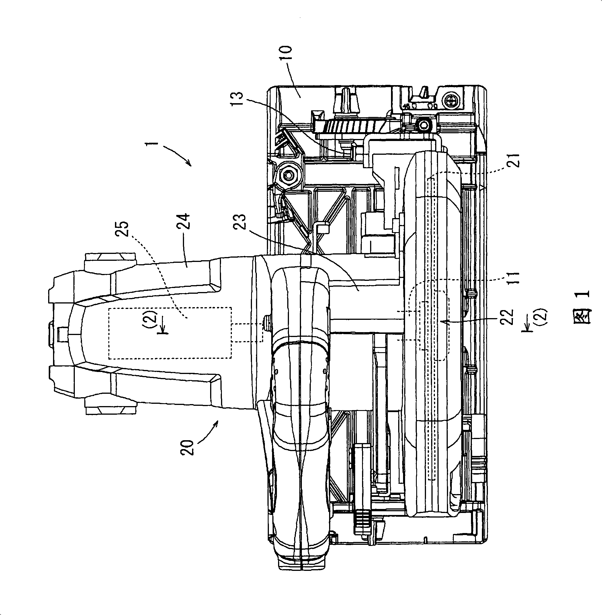
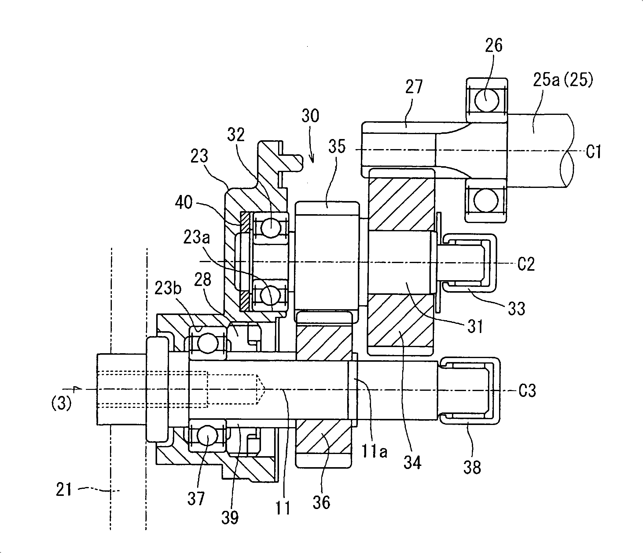
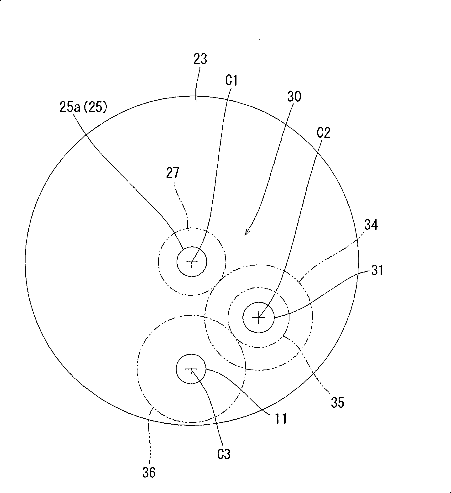
[0029] Next, refer to Figure 1~ image 3 Embodiments of the present invention will be described. Fig. 1 shows a complete cutting machine 1 in which a reduction mechanism as an embodiment of the present invention is used. In this embodiment, a portable circular saw will be described as an example of a cutting machine. This cutter 1 has a structure in which a cutter main body 20 is supported by a support shaft 13 on the upper surface side of a flat base 10 (the side facing out of the paper in FIG. 1 ) so as to be swingable upward and downward. , when working, the base 10 is placed on the material to be processed.

[0030] The cutting machine main body 20 has a blade guard 22 covering approximately the upper half of the circular saw blade 21 . The front end portion of the blade guard 22 in the cutting direction is supported by the above-mentioned support shaft 13, and the blade guard 22 can swing vertically. A gear case 23 is attached to the rear surface (upper side in FIG. 1...


PUM


Abstract

The present invention provides a secondary retarding mechanism of an electric tool, wherein the retarding mechanism is used to retard the output revolution speed of the motor and output it to the main shaft, an axial thrust is acted on an intermediate shaft through the mesh of a beveled wheel so that the intermediate shaft vibrates along the axial direction to produce noises. The object of the present invention is to restrain the intermediate shaft vibration and noise of a portable fretsaw with a secondary retarding mechanism adopting beveled wheels. The secondary retarding mechanism has the following structure that an intermediate shaft can be supported in a mode of moving along the axial direction, the teeth directions of two beveled wheels supporting the intermediate shaft are identical, accordingly a forward axial thrust is acted on the intermediate shaft, the axial thrust is configured to bear by a buffering component on the front side of the intermediate shaft to absorb the vibration.

Description

technical field [0001] The present invention relates to a reduction mechanism used in an electric tool such as a portable circular saw, which reduces the output speed of a motor as a driving source and transmits it to a spindle. Background technique [0002] For example, Patent Document 1 below discloses a technology related to the speed reduction mechanism in the above-mentioned portable circular saw. The structure of the deceleration mechanism in this prior art is as follows: an intermediate shaft is arranged between the output shaft of the motor as the drive source and the main shaft on which the saw blade is installed, and two helical gears (helical gears) as intermediate gears are provided on the intermediate shaft. gear), thereby reducing the output speed of the motor in two stages, wherein, one intermediate gear meshes with the driving gear of the motor output shaft, and the other intermediate gear meshes with the output gear on the main shaft side, and the two interm...

Claims


Application Information

Patent Timeline
IPC IPC(8): F16H1/22F16H1/24F16H57/00B23D47/12B25F5/00
Inventor 松原功治中嶋辰夫福冈彻
Owner MAKITA CORP
Why Eureka
Try Eureka