Direct frequency-output vibration gyroscope structure

A technology of output frequency, vibrating gyroscope, applied in the direction of gyro effect for speed measurement, gyroscope/steering induction equipment, piezoelectric effect/electrostrictive or magnetostrictive motor, etc., to improve sensitivity and measurement accuracy, suppress common The effect of mode interference and anti-interference ability enhancement

Inactive Publication Date: 2009-04-08
BEIHANG UNIV
View PDF0 Cites 17 Cited by
  • Summary
  • Abstract
  • Description
  • Claims
  • Application Information

AI Technical Summary

Problems solved by technology

Therefore, the accuracy of the resonant gyroscope using capacitance detection must be restricted by the bottleneck of weak capacitance detection.

Method used


Image

  • Direct frequency-output vibration gyroscope structure
  • Direct frequency-output vibration gyroscope structure
  • Direct frequency-output vibration gyroscope structure

Examples


Embodiment Construction

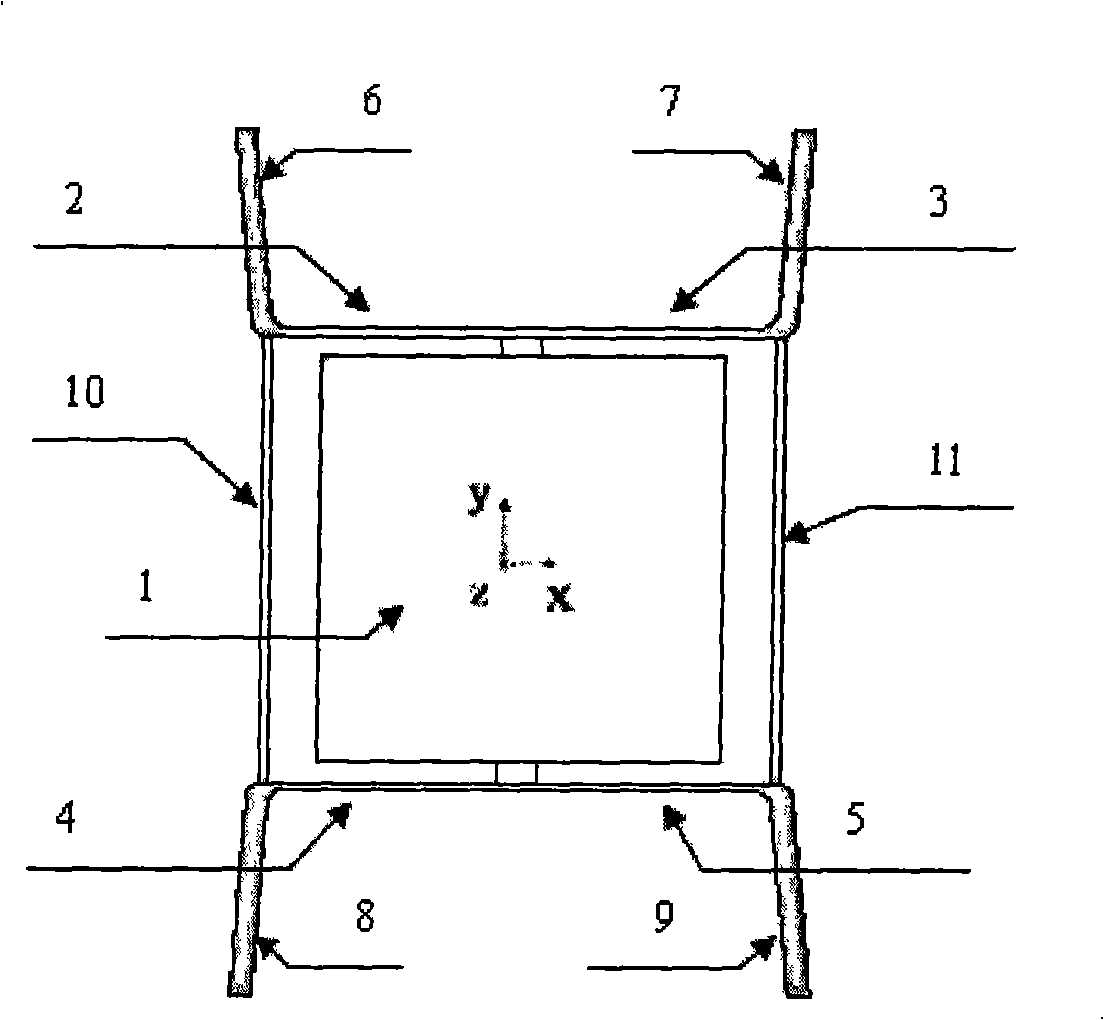
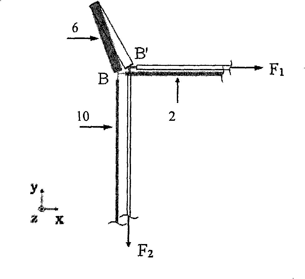
[0015] Such as figure 1 As shown, the vibrating gyroscope structure of the direct output frequency of the present invention comprises a mass block 1, a first elastic support 2, a second elastic support 3, a third elastic support 4 and a fourth elastic support 5, and the first vertical outward deviation is 5° The support arm 6, the second vertically deflected 5° support arm 7, the third vertically deflect 5° support arm 8, the fourth vertically deflect 5° support arm 9, the first resonant beam 10 and the second resonant beam 11. The mass block 1 forms a first-order resonance system with the first elastic support 2, the second elastic support 3, the third elastic support 4 and the fourth elastic support 5. The four supports are all placed horizontally. The first elastic support 2 and the second elastic support The support 3 is connected to the center of the top of the mass block 1 , and the third elastic support 4 and the fourth elastic support 5 are connected to the center of ...


PUM


Abstract

The invention discloses a direct frequency output vibratory gyroscope structure, the aim is to design and manufacture a frequency modulation output vibratory gyroscope based on the plane manufacturing technology, so that the output signal anti-interference capability of the vibratory gyroscope is improved. The design of the vibratory gyroscope is characterized in that: (1) by adopting frequency local modulation means, the signal loss is greatly reduced, and the weak Coriolis effect localized frequency modulation is achieved; (2) by adopting a frame mass block supporting structure, the transverse Coriolis acceleration is correspondingly and significantly enlarged, which is effectively imposed on the axial direction of a resonator beam; (3) two resonator beams adopt a differential resonant structure, and a plurality types of the common-mode interferences can be inhibited, such as temperature stress; and (4) the plane project design is easy to adapt to the related technology of wire cutting machining or MEMS, and is easy to be miniaturized.

Description

technical field [0001] The invention relates to a vibrating gyroscope structure, in particular to a vibrating gyroscope structure directly outputting frequency, which belongs to the overall structure design direction in the field of resonant gyroscope design. Background technique [0002] Various micromechanical vibrating angular rate gyroscopes at home and abroad except Roger T.Howe of Berkelay (Ashwin A.Seshia, Roger T. Howe, and Stephen Montague: An Integrated Microelectromechanical Resonant Output Gyroscope[J].15th IEEE Micro Electro Mechanical Systems Conference, 2002. (1): 20-24) Most of the frequency output frame angular rate gyroscopes use capacitance to detect the vibration of the resonant mass, which is essentially vibration amplitude detection, which is inevitably restricted by the detection accuracy of weak capacitance. The capacitance level is generally 1-10pF, and the peak-to-peak value of the change is generally 0.1-10fF. Due to the small value of capacitance...

Claims


Application Information

Patent Timeline
Patent Type & Authority Applications(China)
IPC IPC(8): G01C19/56B81B7/02G01C19/5656
Inventor 庄海涵樊尚春郭占社
Owner BEIHANG UNIV
Why Eureka
Try Eureka