Framework-taking optical fiber ring detaching device of optic fiber gyroscope

A technology for dismantling devices and fiber optic gyroscopes, which is applied to Sagnac effect gyroscopes, etc., can solve the problems of phase noise generated by the receiver, unsatisfactory results, time-consuming and labor-intensive problems, and achieve high pass rate, easy processing, and flexible applications change effect

Inactive Publication Date: 2009-04-08
HARBIN ENG UNIV
View PDF2 Cites 14 Cited by
  • Summary
  • Abstract
  • Description
  • Claims
  • Application Information

AI Technical Summary

Problems solved by technology

Changes in stress in turn cause changes in fiber propagation constants and fiber dimensions, which also introduce phase noise in the receiver
The traditional way of winding optical fiber rings is the skeleton structure used above, after all, it will be affected by the stress caused by the above-mentioned various reasons, and the corresponding compensation technology has to be adopted, which is time-consuming and laborious, and the effect is not ideal

Method used


Image

  • Framework-taking optical fiber ring detaching device of optic fiber gyroscope
  • Framework-taking optical fiber ring detaching device of optic fiber gyroscope
  • Framework-taking optical fiber ring detaching device of optic fiber gyroscope

Examples


Embodiment Construction

[0018] The present invention is described in more detail below in conjunction with accompanying drawing example:

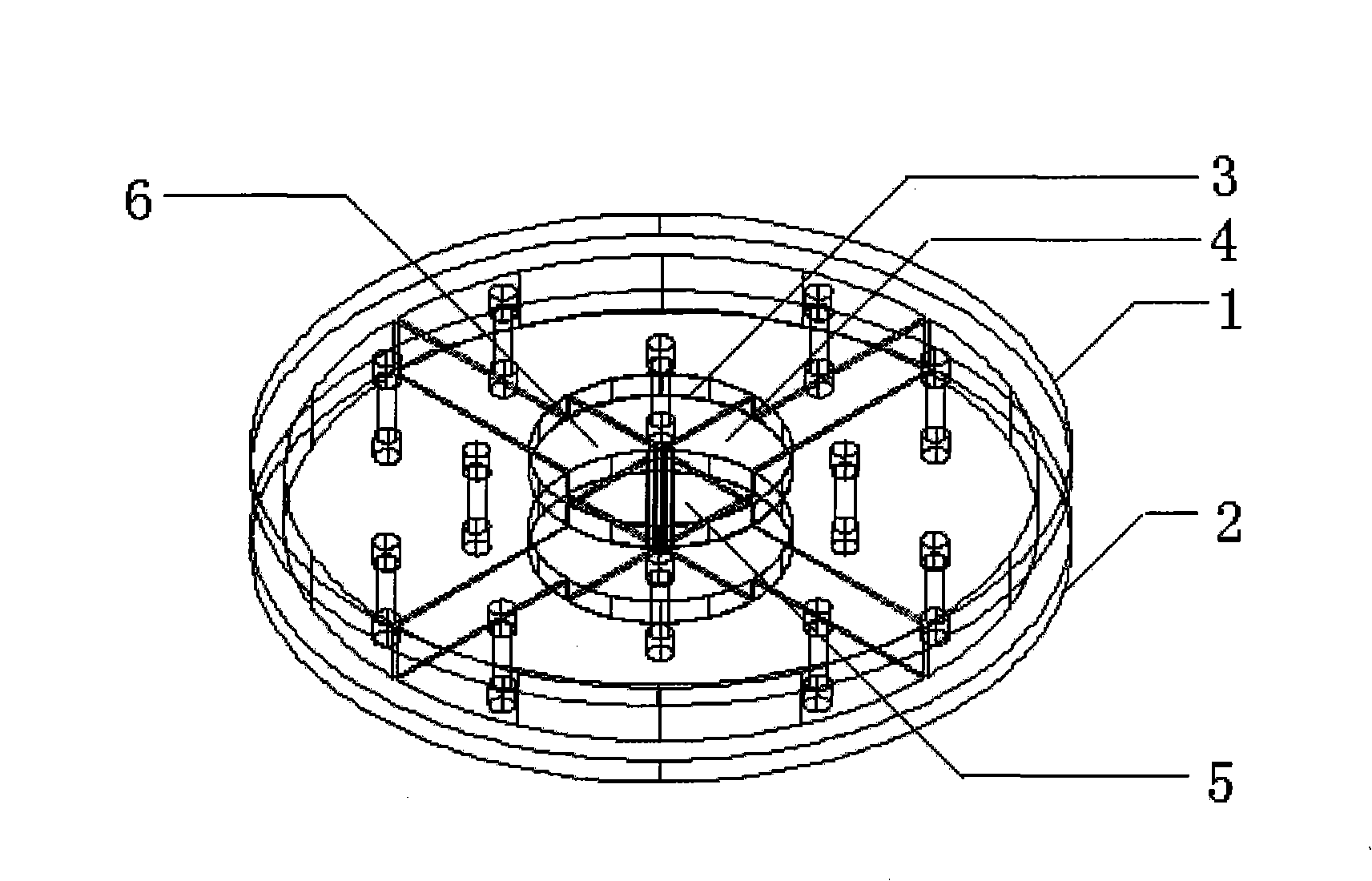
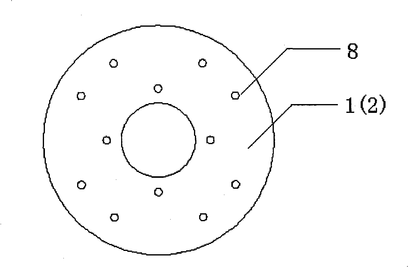
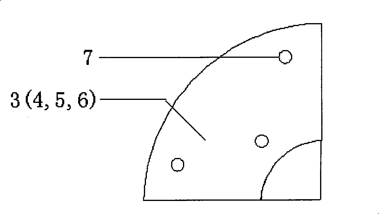
[0019] to combine figure 1 and Figure 5 The fiber optic gyroscope deskeleton fiber ring removal device consists of two discs 1 and 2 of the same specification, and four fan pages 3, 4, 5 and 6 of the same specification that can be combined into a disc. Combining both Figure 3 and Figure 4 , each leaf has a positioning step 9 and mounting holes 7 are evenly distributed on both sides. Simultaneously combine figure 2 and Figure 4 , there are mounting holes 8 corresponding to the mounting holes 7 on the fan leaf on the surface of the disc. The fan blades are four 90° fan pages. There are three mounting holes on each fan.

[0020] The optical fiber can be wound on the optical fiber winding reel according to different winding processes and packaging processes. After it is cured and glued, the fiber optic gyroscope deskeleton fiber ring disassembly device can ...


PUM


Abstract

The invention provides a fiber gyroscope non-frame fiber ring disassembly device, comprising two disks with same specifications, a set of fans with same specifications which can form a disk. Each fan is provided with positioning steps and installation holes on the both sides, the center of the disk is provided with a positioning hole, and the surface of the disk is provided with installation holes corresponding to the installation holes of the fans. The disassembly device can overcome the stress influence of the traditional fiber ring winding program due to the existing frame. The disassembly device application of the fiber gyroscope non-frame fiber ring is flexible, and has high adaptable capability to the environment, which can be applicable to a variety of fibers and a variety of fiber technical fields. The parts of the fiber gyroscope non-frame fiber ring disassembly device in the invention have the advantages of simple structure, easy processing, and high yield. Simultaneously, the fiber gyroscope non-frame fiber ring disassembly device in the invention uses hard aluminum alloy, the deformation coefficient is small, the pass rate of the winding fiber ring is high, and the efficiency is high.

Description

(1) Technical field [0001] The invention relates to a dismantling device, in particular to a dismantling device of an optical fiber gyroscope deskeleton fiber ring. (2) Background technology [0002] In the field of optical fiber sensing technology, it is often necessary to use various specifications of optical fibers to wind fiber rings, and the wound fiber rings require different winding processes according to different application environments and usage methods. Fiber optic gyroscope is an important fiber optic angular velocity sensor. Due to its unique advantages: small size, high precision, large dynamic range, no mechanical rotating parts, etc., it is more and more favored by universities and research institutes. It is widely used in various inertial navigation systems. Its sensing part is an optical fiber ring made of polarization-maintaining optical fiber. This requires high requirements for the wound sensing fiber ring. Traditional optical fiber rings have a skel...

Claims


Application Information

Patent Timeline
Patent Type & Authority Applications(China)
IPC IPC(8): G01C19/72
Inventor 李绪友吴磊于强陈广王刚周广涛陈世同张琛高洪涛
Owner HARBIN ENG UNIV
Why Eureka
Try Eureka