
Touch detection method, apparatus and system

A technology of touch detection and touch panel, applied in instruments, electrical digital data processing, magnetic sensor arrays, etc., can solve the problems of easy misjudgment, very complicated judgment, weak capacitance, etc., to improve detection accuracy and avoid human factors Even the effect of environmental factors

Inactive Publication Date: 2009-04-08
HUAWEI DEVICE (SHENZHEN) CO LTD
View PDF0 Cites 17 Cited by
  • Summary
  • Abstract
  • Description
  • Claims
  • Application Information

AI Technical Summary

Problems solved by technology

After a long time of use, the screen will produce a blurry screen, which will affect the appearance and continue to use
Capacitive touch screen technology mainly relies on detecting the capacitance change between the human finger and the sensing body to achieve the purpose of detecting the position of the finger, but the capacitance generated by the finger is very weak, and it is not related to the temperature and humidity of the environment, and even the cleanliness of the finger, gender, Ethnicity may be related, so the judgment of the capacitance change of the contact point is very complicated, and it is easy to cause misjudgment
In addition, the resistive touch screen and the capacitive touch screen are all above the display screen, which will hinder the light transmission of the screen and affect the display effect.

Method used


Image

  • Touch detection method, apparatus and system
  • Touch detection method, apparatus and system
  • Touch detection method, apparatus and system

Examples


Embodiment 1

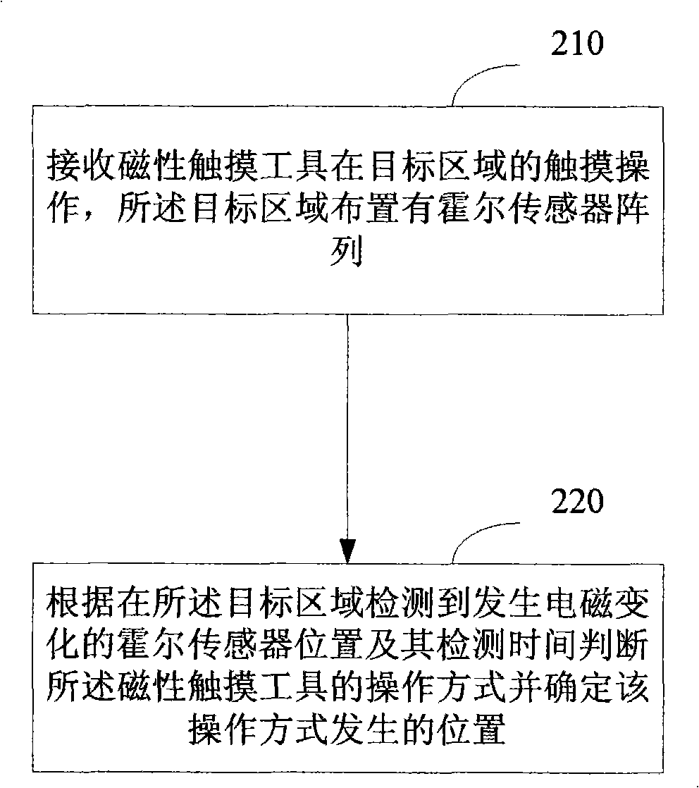
[0028] An embodiment of the present invention provides a touch detection method, see figure 2 , including the following steps:

[0029] 210: Receive a touch operation of a magnetic touch tool on a target area, where a Hall sensor array is arranged in the target area;

[0030] 220: Judging the operation mode of the magnetic touch tool according to the position of the Hall sensor where the electromagnetic change is detected in the target area and the detection time, and determining the position where the operation mode occurs.

[0031] The embodiment of the present invention realizes the detection of the touch operation by arranging the Hall sensor array, and at the same time avoids the influence of human factors or even environmental factors caused by using fingers or the like as touch tools, and improves the detection accuracy.

Embodiment 2

[0033] The Hall Effect defines the relationship between the magnetic field and the induced voltage, which is completely different from the traditional induction effect. When the applied external magnetic field is perpendicular to the current flowing in the semiconductor, a Hall electromotive force will be generated in the semiconductor in the direction perpendicular to the magnetic field and the current, which is the Hall effect.

[0034] The Hall sensor is made on the basis of the Hall effect principle. According to the Hall effect, people use semiconductor materials to make Hall sensors, which have the advantages of sensitivity to magnetic fields, simple structure, small size, wide frequency response, large output voltage changes, and long service life. Therefore, in measurement, automation, computer and Information technology and other fields have been widely used.

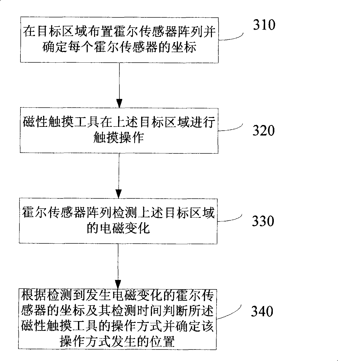
[0035] On this basis, the embodiment of the present invention provides a touch detection method, such as ...

Embodiment 3

[0049] An embodiment of the present invention provides a touch detection device, see Figure 4 ,include:

[0050] The touch receiving module 401 is configured to receive a touch operation of a magnetic touch tool on a target area.

[0051] The touch detection module 402 is used for judging the operation mode of the magnetic touch tool and determining the position where the operation mode occurs according to the position of the Hall sensor where the electromagnetic change is detected in the target area and the detection time.

[0052] Further, the touch detection module 402 includes:

[0053] The sliding detection unit 403 is used to determine that the operation mode of the magnetic touch tool is sliding when a plurality of adjacent Hall sensors in the target area successively detect that the magnetism changes from non-existent to non-existent and then to non-existent. The sliding trajectory is determined by the position of the Hall sensor where the electromagnetic change occ...


PUM


Abstract

The invention discloses a touch detection method, a device and a system thereof, belonging to the touch detection technical field. The method includes: touch operation of a magnetic touch tool in a target area in which a hall sensor array is arranged is received; the operation mode of the magnetic touch tool is judged according to the position of the detected hall sensor, electromagnetism of which is changed, in the target area and the detection time, and the occurring position of the operation mode is determined. The device comprises a touch receiving module and a touch detecting module. The system comprises a touchpad and a magnetic touch tool which is used for touching the touchpad; wherein, the touchpad consists of a touch receiving module and a touch detecting module. The invention realizes the detection on touch by the hall sensor array and avoids the influence of man-induced factor caused by using touch tools such as fingers, and the like, and even the environment factor, thus improving the detection precision.

Description

technical field [0001] The invention relates to the technical field of touch detection, in particular to a touch detection method, device and system thereof. Background technique [0002] The input interface of traditional personal computers or workstations has inherent limitations, and cannot achieve the purpose of fast transmission and exchange of information. The reason is that a keyboard or mouse must be used to promote communication between humans and computers. This input device is not suitable for computers. It is a serious entry barrier for people with operational skills, which will greatly reduce the purpose of information exchange. In order to meet the needs of fast information exchange, the use of non-keyboard and non-mouse input methods will largely replace the existing communication methods between people and information equipment. At present, the most mature non-keyboard and non-mouse input method is touch detection technology, that is, the use of a touch scre...

Claims


Application Information

Patent Timeline
Patent Type & Authority Applications(China)
IPC IPC(8): G06F3/046
CPCG01R33/0094
Inventor 张志淳
Owner HUAWEI DEVICE (SHENZHEN) CO LTD
Learn More