
Power transmission unit and method for assembling same

A power transmission device and power transmission technology, applied in the direction of power device, electric power device, pneumatic power device, etc., can solve the problems of insufficient space, inapplicability, increased components, etc., and achieve simple and easy oil circuit structure. Assembly effect

Inactive Publication Date: 2011-11-23
TOYOTA JIDOSHA KK +1
View PDF5 Cites 0 Cited by
  • Summary
  • Abstract
  • Description
  • Claims
  • Application Information

AI Technical Summary

Problems solved by technology

As described in the aforementioned Japanese Patent Application Laid-Open No. 2005-117807 and Japanese Patent Laid-Open No. 2002-165420, if guide members or guide pins are provided, the rotor can be held concentrically with the stator. Installing guide members, guide pins, and other members used only for assembly may result in an increase in the number of components, and may increase the number of processes when disassembling parts.
Also, it is not suitable for installations that do not have enough space due to the space required for guide members and guide pins

Method used


Image

  • Power transmission unit and method for assembling same
  • Power transmission unit and method for assembling same
  • Power transmission unit and method for assembling same

Examples


Embodiment Construction

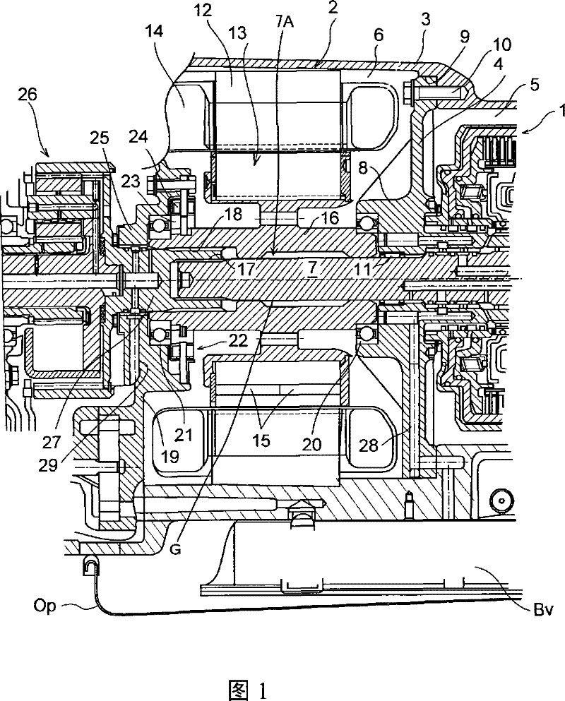
[0053] Hereinafter, the present invention will be described based on specific embodiments shown in the drawings. figure 1 It is a sectional view showing a part of the power transmission device which is the object of the present invention. The power transmission device shown in the figure has a mechanical transmission unit 1 and an electric motor 2 . The speed change unit 1 and the electric motor 2 are housed inside a housing 3 . The structure of the housing 3 is that one end side ( figure 1 The left side in the middle) is a larger opening, and the other end side ( figure 1 The right side in ) is a small opening through which an output shaft (not shown) can penetrate, and is divided into two storage chambers 5 and 6 by a partition wall 4 installed inside the housing 3 . Furthermore, the transmission unit 1 is arranged in figure 1 In the storage chamber 5 on the right side, in addition, the motor 2 is arranged in figure 1 The storage chamber 6 on the left side is adjacent t...


PUM


Abstract

Assembling performance of a motor contained in a case contiguously to a transmission mechanism in a power transmission unit is enhanced. The power transmission unit comprises a motor (2) having a rotor (13) disposed on the inner circumferential side of a stator (12) concentrically to the stator (12), and a transmission mechanism (1) for transmitting power wherein a part (7) of a predetermined constitutional member in the transmission mechanism (1) projects to the side of the stator (12) or the rotor (13), and the rotor (13) is attached concentrically to the stator (12) while being guided by the projecting portion. The rotor (13) can be attached under a state substantially supported at the opposite ends even if the space of a chamber for containing the motor (2) has one closed end.

Description

technical field [0001] The present invention relates to a power transmission device having a transmission mechanism such as a transmission and a motor for increasing or decreasing torque input to or output from the transmission mechanism and a method for assembling the same. Background technique [0002] Conventionally, as a power plant for a vehicle, a device combining an internal combustion engine and an electric motor and a device using an electric motor as a power source are known. In order to control the driving torque and the number of revolutions of the internal combustion engine or the electric motor, a vehicle using such a power plant is also equipped with a transmission. One example thereof is disclosed in Japanese Patent Application Laid-Open No. 2003-127681. The device described in Japanese Patent Application Laid-Open No. 2003-127681 is a driving device for a hybrid vehicle, in which an internal combustion engine is connected to a planetary gear carrier of a pl...

Claims


Application Information

Patent Timeline
Patent Type & Authority Patents(China)
IPC IPC(8): H02K7/10B60K6/20B60K17/04B60L11/14B60K6/26B60K6/40B60K6/445B60K6/547B60L50/16
CPCB60W2510/0638B60W2540/12Y02T10/6239B60W10/30B60W10/06B60L2240/445B60W2510/0676B60W2520/10B60K6/40B60W2540/10B60L2240/441B60W20/00F16H2037/0866B60K6/547B60W2710/0605F16H2200/2046B60W2540/16H02K51/00B60K6/445F16H2200/2012B60W2520/28F16H2200/0043B60W2510/105B60W2510/107B60W10/115B60L2240/485B60W2520/125B60K6/405B60K1/02Y02T10/6286B60L2240/486B60W2510/0685B60W10/08B60L2240/421B60W2710/0616B60W2530/10Y02T10/642B60W2510/081B60W2510/068F16H3/728B60K6/365Y02T10/641Y10T74/2186Y10T29/49002Y02T10/62Y02T10/64B60W20/30
Inventor 田端淳北条康夫小嶋昌洋茨木隆次柿并拓马早川圣糟谷悟鬼头昌士
Owner TOYOTA JIDOSHA KK
Learn More