Timing automatic ball-throwing apparatus and method

A pitching device and automatic technology, applied in chemical instruments and methods, cleaning methods and tools, earthwork drilling and mining, etc., can solve problems such as difficult automatic control, achieve significant economic benefits, solve manual operations, and reduce human resources. Effect

Inactive Publication Date: 2009-04-15
XIAN CHANGQING TECH ENG
View PDF0 Cites 22 Cited by
  • Summary
  • Abstract
  • Description
  • Claims
  • Application Information

AI Technical Summary

Problems solved by technology

Due to the large temperature difference between the ground and the underground, after the crude oil is pumped out of the ground, a large amount of wax will be precipitated and adhered to the inner wall of the oil pipeline. If it is not cleaned for a few days, the oil pipeline will be blocked. Pipelines and long-distance pipelines need to throw balls to remove wax, so oil production workers need to go to the well site to throw balls into the oil pipeline every day to remove wax. There are about tens of thousands of oil wells in a large oil field, and each well is manually thrown every day, requiring a large number of personnel and vehicles Cooperate, over the past few decades, the pitching device has undergone many improvements. Although it is a mature technology, it has not gotten rid of the cumbersome manual operation, that is, every time the ball is thrown, the two valves at the front and rear of the pitching device are first closed, and then the ball is released. Then put the wax removal ball into the pipeline; open the two valves before and after the ball throwing device, and push the wax removal ball into the oil pipeline. Such a cumbersome operation is difficult to achieve automatic control, so there is an urgent need for a timing automatic ball throwing system. device to reduce the cost of oil production and reduce the labor intensity of employees

Method used


Image

  • Timing automatic ball-throwing apparatus and method
  • Timing automatic ball-throwing apparatus and method

Examples


Embodiment Construction

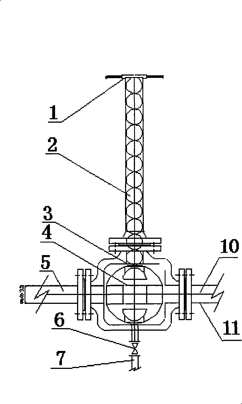
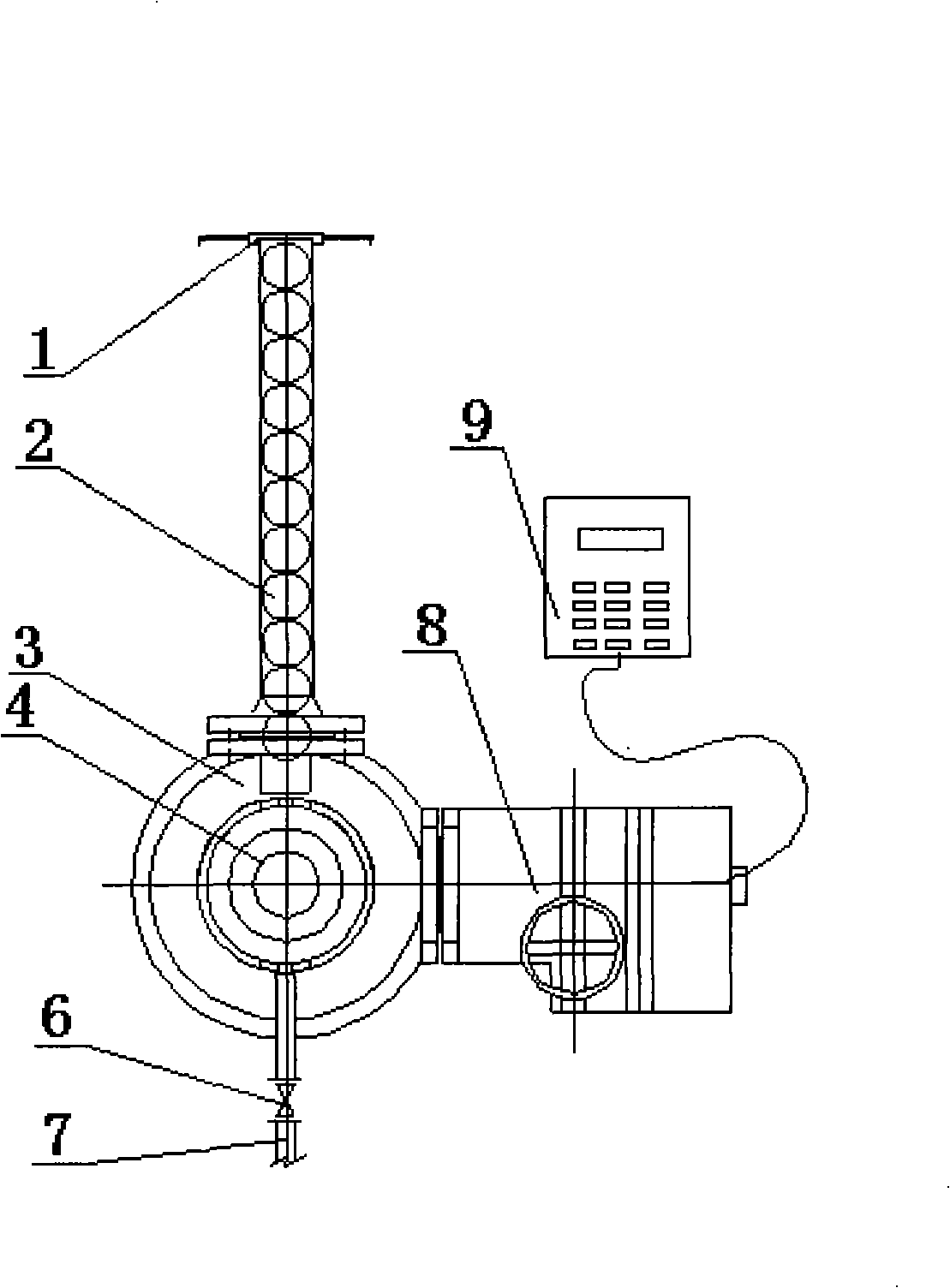
[0023] Such as figure 1 , figure 2 As shown, it includes a ball loading cylinder 1, a control valve 3 and a control unit 9. The ball loading cylinder 1 is vertically connected to the upper port of the control valve 3 through a flange. The upper end of the ball loading cylinder 1 is the inlet of the wax removal ball 2, and the lower end is The outlet of the wax ball 2 and the outlet of the wax removal ball 2 are connected to the control valve port of the connecting pipeline 11. The control valve 3 is a ball valve, and the ball valve 3 is connected between the crude oil input pipeline 5 and the crude oil output pipeline 10. The core 4 rotates 90 degrees, and the wax removal ball 2 of the ball tube 1 will remove the wax in the direction of the crude oil output pipeline 10. The ball valve spool 4 opens a circular hole in the direction of 90 degrees of the original flow direction, and the cross-sectional area of ​​the hole is not less than 1 / 2 the cross-sectional area of ​​the pi...


PUM


Abstract

The invention belongs to oil production and oil collecting equipment of an oil field, and relates to a ball injector in production and establishing engineering of the oil field, in particular to a timing automatic ball injector and a method thereof. The ball injector is characterized by comprising a ball-packing cylinder (1), a control valve (3) and a control unit (9); one end of the ball-packing cylinder (1) is an inlet for paraffin removal balls (2), and the other end thereof is an outlet for the paraffin removal balls (2); the outlet for the paraffin removal balls (2) is connected with a port of the control valve (3) of a connecting pipeline (11); the control valve (3) is a ball valve which is connected between a crude oil input pipeline (5) and a crude oil output pipeline (10); a ball valve core (4) is turned by 90 degrees through an electric head (8) of the control ball valve; the paraffin removal balls (2) of the ball-packing cylinder (1) carry out paraffin removal along the direction of the crude oil output pipeline (10); the ball valve core (4) is turned to be reset through the electric head (8) of the control ball valve; and the paraffin removal balls (2) of the ball-packing cylinder (1) are blocked. The ball injector can be used for reducing the cost of oil production and reducing the labor intensity of employees.

Description

technical field [0001] The invention belongs to oil extraction and oil collection equipment in an oil field, and relates to a ball throwing device in an oil field production and construction project, in particular to a timing automatic ball throwing device and method. Background technique [0002] At present, oil production and oil collection methods in various oil fields are transported from oil wells to oil gathering stations or centralized processing stations using single well pipelines. Due to the large temperature difference between the ground and the underground, after the crude oil is pumped out of the ground, a large amount of wax will be precipitated and adhered to the inner wall of the oil pipeline. If it is not cleaned for a few days, the oil pipeline will be blocked. Pipelines and long-distance pipelines need to throw balls to remove wax, so oil production workers need to go to the well site to throw balls into the oil pipeline every day to remove wax. There are ...

Claims


Application Information

Patent Timeline
Patent Type & Authority Applications(China)
IPC IPC(8): E21B37/00B08B9/04
Inventor 王晓东朱天寿杨世海王文武李永生郭亚红
Owner XIAN CHANGQING TECH ENG
Why Eureka
Try Eureka