Diversion shield tunnel traversing new sea dyke and foundation treatment method thereof

A technology for water diversion shield tunnel and foundation treatment, applied in tunnels, tunnel linings, underground chambers, etc., can solve the problems of slow consolidation speed, high compressibility, poor grouting effect, etc., and improve the lateral stress state. , the effect of preventing damage

Active Publication Date: 2009-04-15
ZHEJIANG ELECTRIC POWER DESIGN INST
View PDF5 Cites 9 Cited by
  • Summary
  • Abstract
  • Description
  • Claims
  • Application Information

AI Technical Summary

Problems solved by technology

[0003] Tidal flat mud has the characteristics of low foundation bearing capacity, high compressibility, low permeability coefficient, and slow consolidation speed. Building seawalls on it often results in large post-construction settlements. The key technology of crossing is how to eliminate the longitudinal fracture of the tunnel caused by the post-construction settlement of the seawall, thus affecting the normal water intake of the power plant
At present, the technical measure often used to solve this problem is to carry out grouting reinforcement in the underlying layer of the tunnel to reduce post-construction settlement. However, this solution is often applicable to shallow silt layers. When the silt is deep, the grouting effect is poor, and it is urgent to find a better foundation treatment method

Method used


Image

  • Diversion shield tunnel traversing new sea dyke and foundation treatment method thereof
  • Diversion shield tunnel traversing new sea dyke and foundation treatment method thereof

Examples


Embodiment Construction

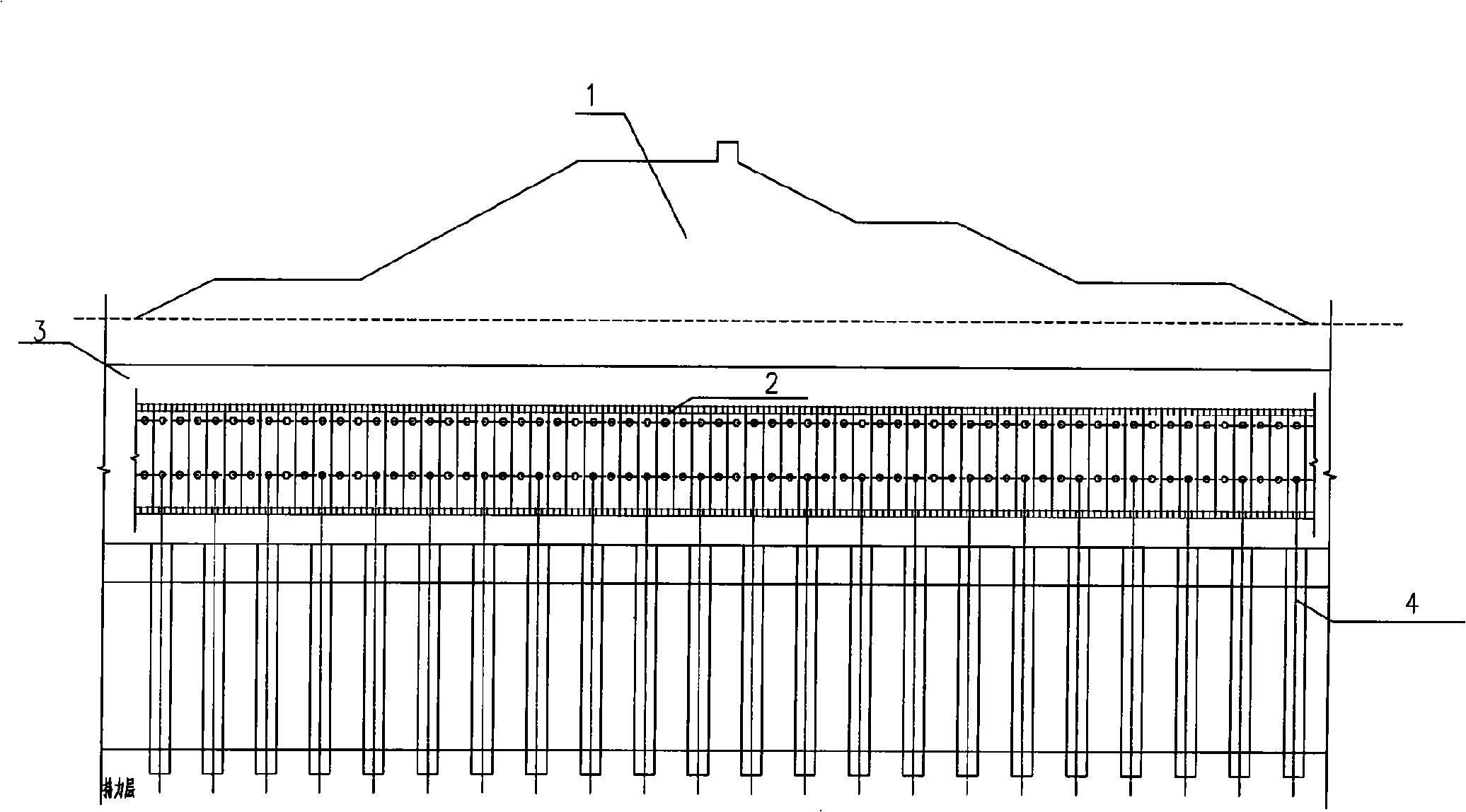
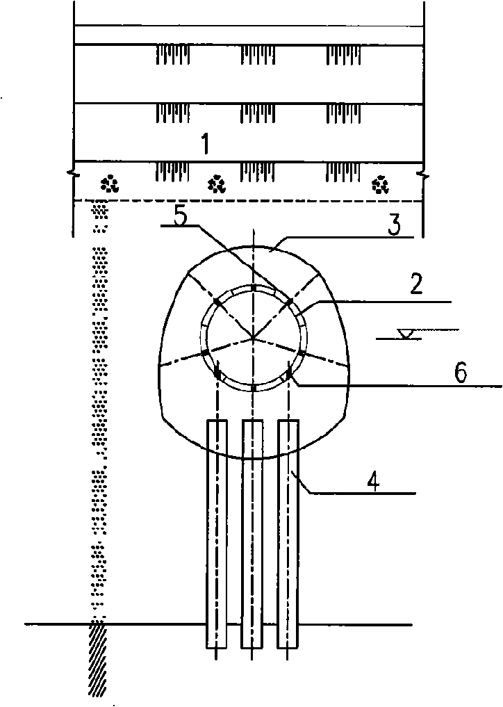
[0011] The present invention will be described in further detail below in conjunction with the accompanying drawings. figure 1 , 2 As shown, the water diversion shield tunnel 2 passing through the newly-built seawall 1 according to the present invention is assembled by a plurality of annular segments through bolts, and the corresponding positions of the segments are preset with compaction grouting holes 5 and High-pressure jet grouting pile operation hole 6; a plurality of high-pressure jet grouting piles 4 are arranged at a certain distance away from the bottom of the segment to form a transition layer, and pass compaction in the mud around the water diversion shield tunnel formed by the segment A reinforcement layer 3 is formed by grouting.

[0012] The water diversion shield tunnel is composed of six circumferential segments 2 spliced ​​in pairs by high-strength bolts to form an overall structure, and the 4 high-pressure rotary grouting piles are separated from the bottom ...


PUM


Abstract

The invention relates to a pilot shield tunnel which crosses a newly-built seawall and a ground treatment method. The pilot shield tunnel is formed by that a plurality of duct pieces are assembled by bolts in a circumferential mode; the corresponding positions of the duct pieces are preinstalled with consolidated filling injection ports and operating ports of a high-pressure jet grouting pile; a plurality of high-pressure jet grouting piles are arranged at a certain distance from the bottom part of the duct pieces and form a transition layer; a reinforcing layer is formed by the consolidated filling injection in the sludge of the pilot shield tunnel which is formed by the duct pieces; the ground treatment method comprises: a plastic draining board is adopted to carry out ground foundation; the corresponding positions of the duct pieces are preinstalled with consolidated filling injection ports and operating ports of the high-pressure jet grouting pile; when the pilot shield tunnel crosses at the lower part of the foundation of the seawall, the construction of high-pressure jet grouting pile is carried out in the soft soil of a lower horizontal layer of the tunnel through the operating ports of the high-pressure jet grouting pile; the bottom of the high-pressure jet grouting pile enters a holding layer; after the construction of the high-pressure jet grouting pile is completed, consolidated filling injection is adopted at the periphery of the shield tunnel, thus having the characteristics of effectively reducing after-construction settlement of the shield tunnel which encounters the lower horizontal layer of the deep soft soil when crossing the newly-built seawall so as to prevent the tunnel from being tension fracture in the lengthways direction and further have influence of taking and draining water, and effectively improving the transverse forced state of the shield tunnel so as to prevent damage caused by the concentrated force on a single duct piece.

Description

technical field [0001] The invention relates to a foundation treatment method for a water diversion shield tunnel crossing a newly built seawall used in conjunction with a seaside power plant, which can solve the post-construction problems that occur when the shield tunnel crosses a newly built seawall and encounters a deep and thick soft soil underlying layer. Settlement and stress concentration problems. Background technique [0002] At present, the economy in the east coast of my country is developing rapidly, and the demand for electricity is large. In order to meet the requirements of economic development in the region and improvement of people's living standards, the country needs to invest huge sums of money every year in the construction of large-scale thermal power plants. The site selection of large-scale thermal power plants should fully consider the convenience and economy of coal transportation, water intake and drainage, as well as factors such as land conserva...

Claims


Application Information

Patent Timeline
Patent Type & Authority Applications(China)
IPC IPC(8): E21D9/14E21D11/04E21D11/10E21D11/38
Inventor 黄建武吴建国童建国朱瑞燕张浙杭张根土李琪吉建兴
Owner ZHEJIANG ELECTRIC POWER DESIGN INST
Why Eureka
Try Eureka