
Gravity engine

An engine and gravity technology, applied in the direction of engines, machines/engines, mechanisms that generate mechanical power, etc., can solve problems such as failure to create, large frictional resistance, and small quantity, so as to overcome the unstable power of a single machine and increase output The effect of energy, simple structure

Inactive Publication Date: 2009-04-15
北京金科奥赛技术研究中心 +2
View PDF0 Cites 5 Cited by
  • Summary
  • Abstract
  • Description
  • Claims
  • Application Information

AI Technical Summary

Problems solved by technology

It has four defects: (1) the size radius R 2 / R 1 The ratio is less than 3, that is, the degree of asymmetry is too small; (2) there are only 4 power heavy wheels, which are too small to form a large dynamic moment; (3) there is no guide rail in the d-h section of the iron ball going up, although the dead angle of movement is avoided, but The upward starting point d is too close to the left side, that is, it is too far away from the vertical line of the axis, which not only lengthens the upward energy consumption distance, but also occupies the section that should belong to the downward work of the iron ball, which shows that the direction of the guide rail is improper; (4 ) The iron ball slides along the spoke rod, the frictional resistance is too large
[0014] The key to all failed solutions is the failure to create a gravitational dynamic torque that can push the rotor to rotate continuously, much greater than the total drag torque

Method used


Image

  • Gravity engine
  • Gravity engine
  • Gravity engine

Examples


Embodiment Construction

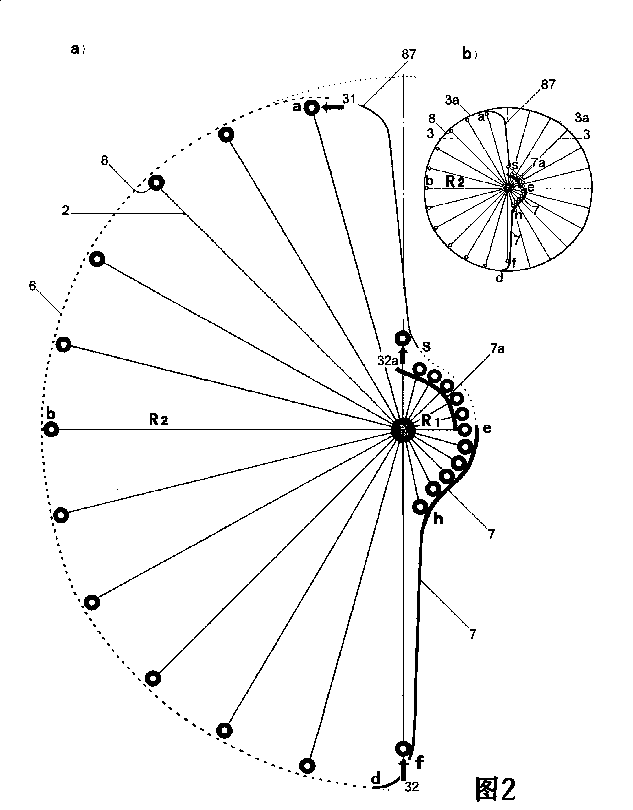
[0059] In addition to Figure 5a, 8, in the following figures, due to the limitation of the drawing, in order to make R 1 Sharp images in visual range, R 2 / R 1 The ratios are all plotted as η<7.

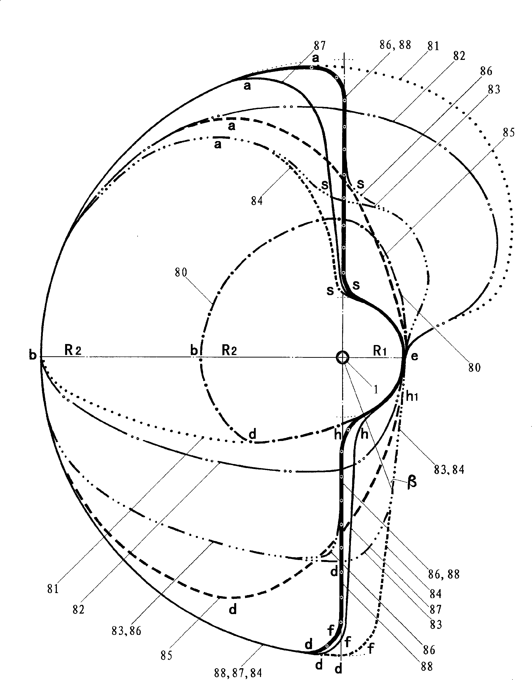
[0060] figure 1 Nine types of stator rails 80-88 involving only straight-spoke-rod 2-type eccentric rotors are given.

[0061] Guide rails 81 and 82 have an inflection point at e, and their uplink e-a section occupies a large area of ​​the first quadrant, that is, the resistance moment M 1 large; while the antisymmetric third quadrant has a small area of ​​work, and the driving moment of gravity M 2 necessarily small.

[0062] If there are inflection points h and s, the small eccentric uplink segment becomes d-f-h-e-s-a.

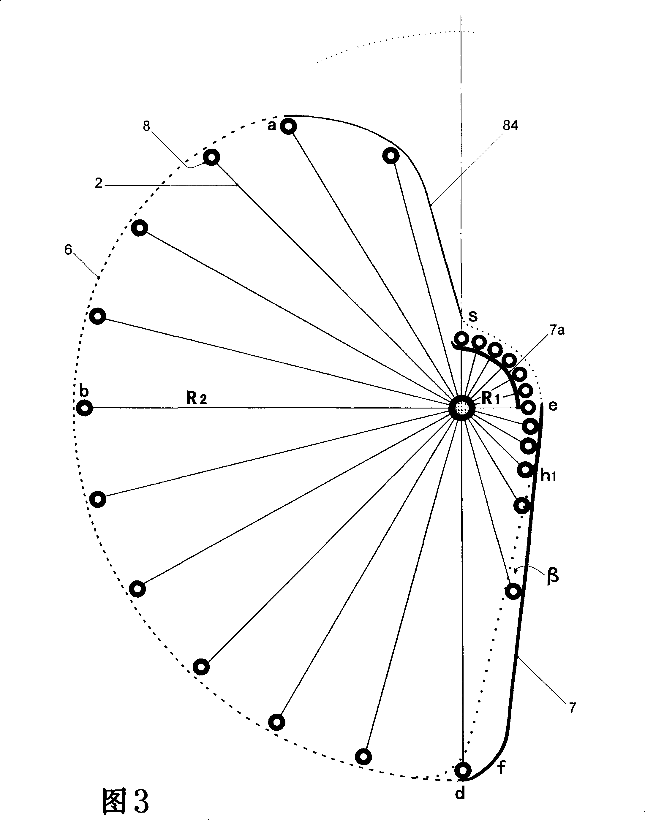
[0063] The guide rails 83 and 84 (see FIG. 3 ) have no lower point of inflection h, but have an upper point of inflection s.

[0064] The guide rail 85 is a well-known vertically symmetrical arc without an inflection point.

[0065] All guide rails 83-85 w...


PUM


Abstract

The invention discloses a gravity engine which comprises an eccentric rotor and a stator guiderail. The ratio Eta of R2 / R1 of the rotor is not less than 7; and the number N0 of radius rods is not less than 24. The radius rod adopts a straight radius rod (2) or a flexible radius rod (20), wherein, the straight radius rod (2) adopts a fixed type (3), a telescopic type (4) or a movable type (5); and the uplink guiderail of the straight radius rod (2) does not have or has an inflexion point h and / or s. The flexible radius rod (20) adopts a semi-hinge type (21), a helical spring type (22) or a lath spring type (23). An instantaneous downlink assistor (31) and / or an uplink assistor are / is adopted. The uplink assistor (32) or (32a) adopts instantaneous force implementation, permanent magnet repulsion, chain-hook pull and separation, chain-hook hoist, connecting rod-spring push, and the like. The original power of the assistor is provided by the self-rotation of the rotor and / or the outside. The total driving gravitational moment is far lager than the total resistance moment, therefore, the rotor is promoted to do continuous rotation work and output energy. The gravity engine can become a new green energy so as to be made into a power machine or a toy. The engine has simple structure, easy manufacturing and low cost.

Description

technical field [0001] The gravity engine of the present invention belongs to power machinery, hereinafter referred to as the gravity machine, and the international patent classification F03G 3 / 00. Background technique [0002] The gravitational energy used by human beings can be divided into fluid water energy and solid heavy object energy according to different carriers --- usually called gravitational energy. It is this carrier difference that makes the nature of gravitational energy appear as a time-independent, ubiquitous, inexhaustible and inexhaustible energy source! [0003] The technology of using gravitational energy and water energy to do work is completely different. Utilizing water energy, that is, the technology of continuous work of a hydraulic engine to output energy, is very mature, while utilizing gravity energy, that is, a continuous work of a gravity engine is on the contrary, and has entered a dead end. In the history of the world, although there have ...

Claims


Application Information

Patent Timeline
IPC IPC(8): F03G3/00F03G7/10
Inventor 祝培钫
Owner 北京金科奥赛技术研究中心
Learn More