Efficient vacuum oil filter

A vacuum oil filter, high-efficiency technology, applied in the direction of filtering and thickening suspension liquid separation, liquid separation, chemical instruments and methods, etc. increase and other problems to achieve the effect of promoting uniform suction, reducing energy consumption, and increasing processing capacity

Pending Publication Date: 2021-05-14
昆山威胜达环保设备有限公司
View PDF1 Cites 0 Cited by
  • Summary
  • Abstract
  • Description
  • Claims
  • Application Information

AI Technical Summary

Problems solved by technology

[0002] Coalescing and separating oil purifiers are commonly used oil purification equipment in the manufacturing industry. However, existing coalescing and separating oil purifiers, such as the coalescing and separating system and the vacuum dehydration system disclosed in Chinese patent CN205699597U, often require a separate Heater and condenser are provided, which have high energy consumption, resulting in high equipment cost and disposal cost
[0003] At present, the existing evaporating devices generally add the evaporated liquid directly into the evaporating tank for evaporation. Although this can save time, due to incomplete evaporation and other reasons, more foam will be generated on the liquid surface, which will affect the evaporation efficiency.
In order to solve this problem, the evaporated liquid is generally evaporated completely by setting a spray device, but limited by the flow rate, this method greatly increases the evaporation time

Method used


Image

  • Efficient vacuum oil filter
  • Efficient vacuum oil filter
  • Efficient vacuum oil filter

Examples


Embodiment 1

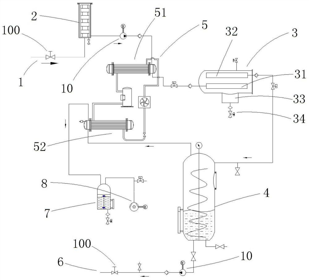
[0030] See Figure 1 to Figure 3 , the high-efficiency vacuum oil filter shown in an embodiment of the present invention includes: an oil inlet pipeline 1, an oil suction filter 2, a coalescing separator 3, an evaporator 4, a heat pump system 5, and an oil outlet pipeline 6, wherein the coalescing separator 3 is provided with a coalescing filter element 31 and a separation filter element 32, which is an existing structure and will not be described in detail here. The oil enters the oil suction filter 2 from the oil inlet line 1, and after removing the insoluble impurities, it is heated by the heat pump system 5 and enters the coalescing separator 3, and most of the water in the oil is removed by the principle of coalescence separation, Moisture is stored in the water storage type 33 and discharged from the drain pipe 34 . Then the oil enters the evaporator 4 for further water removal, the water vapor in the evaporation process is condensed by the heat pump system 5 , and the ...

Embodiment 2

[0041] See Figure 4, the structure of the high-efficiency vacuum oil filter of this embodiment is basically the same as that of Embodiment 1, the difference is that: in this embodiment, the oil outlet pipeline 6 is also connected to the coalescing separator 3 . Specifically, the oil outlet pipeline 6 includes a main pipeline 61, an oil pump 10 arranged on the main pipeline 61, a first pipeline 62 connecting the oil outlet and the main pipeline 61, and a second pipeline 62 connecting the coalescence separator 3 and the main pipeline 61. pipeline63. Valve structures 100 are respectively provided on the main pipeline 61 , the first pipeline 62 and the second pipeline 63 .

[0042] This design method can facilitate the replacement of the filter element (coalescing filter element 31 and / or separation filter element 32) for the coalescer separator 3. When the filter element needs to be replaced, the residual oil in it can be pumped out through the second pipeline.

Embodiment 3

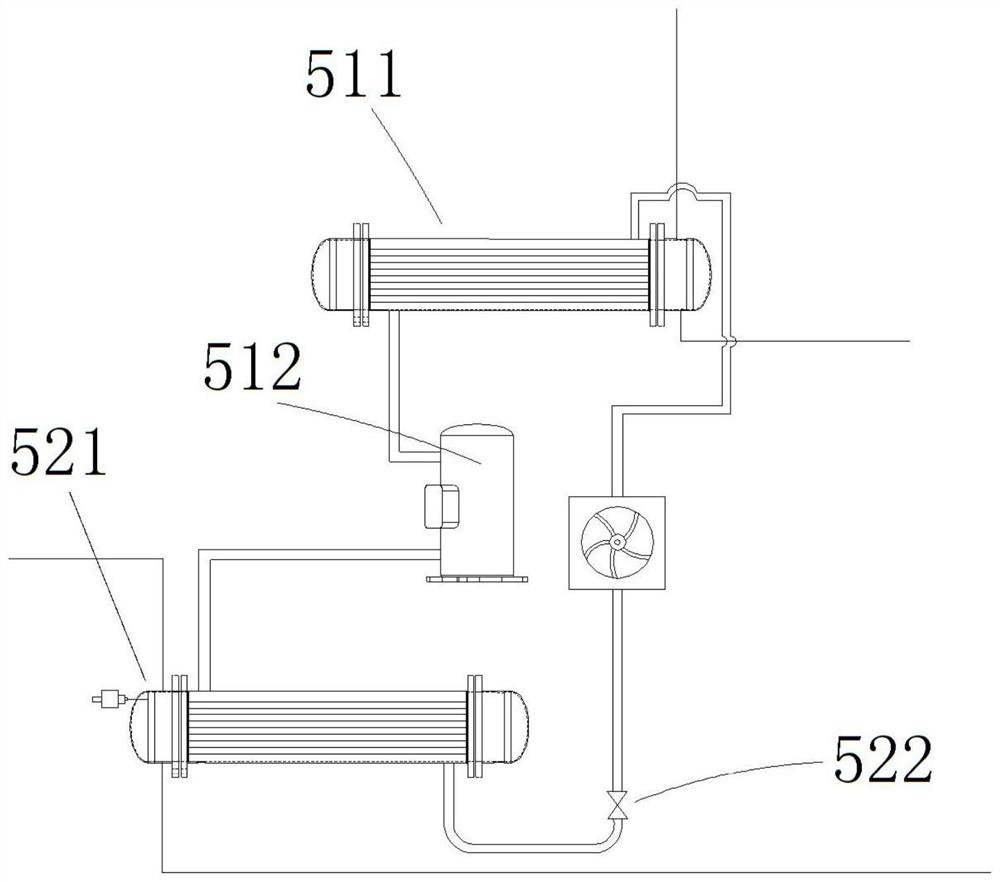
[0044] See Figure 5 to Figure 8 , the structure of the high-efficiency vacuum oil filter of this embodiment is basically the same as that of Embodiment 1 or Embodiment 2, the difference lies in the heat pump system. In this embodiment, the heat source device further includes an inlet port 13 connected to the second heat exchanger 21, and the compressor unit 12 includes a plurality of compressors 121 arranged in parallel, and each compressor 121 is respectively connected to the inlet port 13 and the first The heat exchanger 11 , the intake port 13 is used to distribute the heat exchange medium into each compressor 121 . In this embodiment, the number of compressors 121 is 4. It is true that in other embodiments, the number of compressors 121 can be selected according to actual needs, and the integrated compressor unit 12 can adopt compression ratios of different sizes. Machine 121 to provide more adjustment stages, so that the cooling capacity output can dynamically match the...


PUM


Abstract

The invention relates to a high-efficiency vacuum oil filter, and the filter comprises a coalescence separator, wherein the coalescence separator is internally provided with a coalescence filter element and a separation filter element; an evaporator which is connected with the coalescence separator, a steam outlet, an oil liquid inlet and an oil liquid outlet are formed in the evaporator, a spiral guide plate and a ventilation plate are arranged in the evaporator, the spiral guide plate is vertically arranged in the evaporator, and the upper end of the spiral guide plate is connected with the oil liquid inlet, so that liquid is guided into the evaporator from the liquid inlet; a heat pump system which comprises a heat source device and a condensing device which are circularly communicated, wherein the heat source device is connected with the coalescence separator, and the condensing device is connected with the steam outlet; and an oil outlet pipeline which is connected with the oil liquid outlet. According to the efficient vacuum oil filter, the heat pump system is adopted for heating and condensation, so the energy consumption is reduced, and the cost is reduced; meanwhile, foam generated in the evaporation process can be reduced, so that the evaporation efficiency is improved.

Description

technical field [0001] The invention relates to a high-efficiency vacuum oil filter, which belongs to the field of oil purification equipment. Background technique [0002] Coalescing and separating oil purifiers are commonly used oil purification equipment in the manufacturing industry. However, existing coalescing and separating oil purifiers, such as the coalescing and separating system and the vacuum dehydration system disclosed in Chinese patent CN205699597U, often require a separate Heaters and condensers are provided, and their energy consumption is high, resulting in high equipment costs and processing costs. [0003] At present, the existing evaporating devices generally add the evaporated liquid directly into the evaporating tank for evaporation. Although this can save time, due to incomplete evaporation and other reasons, more foam will be generated on the liquid surface, which will affect the evaporation efficiency. In order to solve this problem, the evaporated...

Claims


Application Information

Patent Timeline
Patent Type & Authority Applications(China)
IPC IPC(8): B01D17/02B01D17/022B01D17/09
CPCB01D17/005B01D17/02B01D17/08
Inventor 路建伟刘威王潘峰
Owner 昆山威胜达环保设备有限公司
Why Eureka
Try Eureka