
Transmission device between working component and rotor of permanent magnetism synchronous electric machine

A permanent magnet synchronous motor and transmission technology, applied in electromechanical devices, pump devices, electrical components, etc., can solve the problems of noise, limit the free travel or free rotation angle of the shaft sleeve, and shake along the axial direction, and reduce contact noise. , avoid collision or contact phenomenon, avoid the effect of starting a large load

Active Publication Date: 2011-01-26
HANYU GRP CO LTD
View PDF2 Cites 3 Cited by
  • Summary
  • Abstract
  • Description
  • Claims
  • Application Information

AI Technical Summary

Problems solved by technology

However, when the rotor rotates, it may vibrate in the axial direction, so that the actuating rib 32a also vibrates in the axial direction, causing the actuating rib 32a to directly collide with the limiting ribs 34a, 34b to generate noise.
In addition, due to the presence of two symmetrically arranged limiting ribs 34a and 34b, the free travel or free rotation angle of the sleeve is also limited.

Method used


Image

  • Transmission device between working component and rotor of permanent magnetism synchronous electric machine
  • Transmission device between working component and rotor of permanent magnetism synchronous electric machine
  • Transmission device between working component and rotor of permanent magnetism synchronous electric machine

Examples


Embodiment Construction

[0057] In order to explain or illustrate the present invention, at first define the following technical terms of the present invention below below:

[0058] Radial refers to the radial direction of the shaft, and axial refers to the axial direction of the shaft;

[0059] The top surface of the activation rib refers to the surface of the highest protrusion of the activation rib protruding from the side wall of the tubular main body of the sleeve;

[0060] The top surface of the limiting rib refers to the highest protruding surface of the limiting rib protruding from the inner wall of the accommodating cavity of the working component;

[0061] The thickness of the shock-absorbing block refers to the difference between the outer arc radius and the inner arc radius of the shock-absorbing block whose cross section is fan-shaped;

[0062] The length of the shock absorber refers to the size of the shock absorber in the direction parallel to the axial direction;

[0063] The length of...


PUM


Abstract

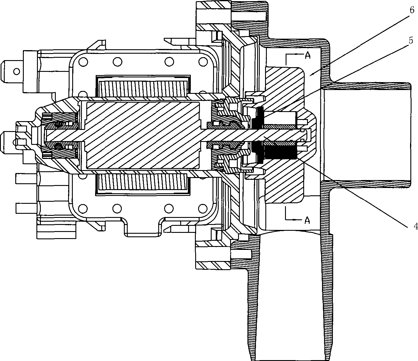
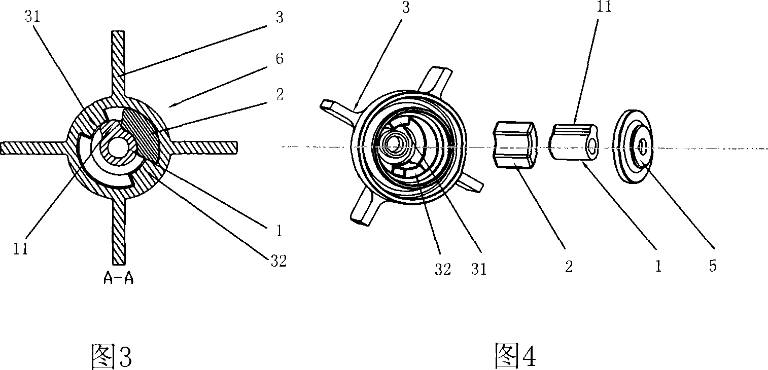
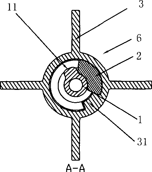
The invention discloses a transmission device between the rotor of a permanent magnet synchronous motor and a working component. The transmission device includes a shaft sleeve which is connected with a rotor shaft, a starting tendon which protrudes out of the side wall of the pipe-shaped main body of the shaft sleeve, a working component with a holding cavity for holding the shaft sleeve, a first limit tendon which protrudes out of the inner wall of the holding cavity of the working component, and a shock absorption block which is held in the holding cavity, wherein, an anti-collision gap isarranged between the top face of the starting tendon and the top face of the first limit tendon so as to prevent the starting tendon from colliding or fractionating the first limit tendon when the shaft sleeve rotates along with the rotor shaft. The device has the technical effect of large free stroke of the shaft sleeve, thus having good low-voltage starting performance.

Description

technical field [0001] The invention relates to a shaft coupling of a permanent magnet synchronous motor, in particular to a transmission device between a rotor and a working member of the permanent magnet synchronous motor. Background technique [0002] US Patent Application Publication No. US2005 / 0111992 discloses a centrifugal drain pump for household appliances. This drainage pump is developed to solve the problems of heavy load and easy burning of the motor when the pump is started, and it mainly improves the starting connection between the shaft sleeve and the impeller. As shown in the drawings of the patent, the patent sets the starting ribs on the shaft sleeve, and sets a limiting rib on the inside of the impeller outwards, wrapping the two sides of the axial radiation of the starting ribs and the limiting ribs. A layer of elastic material is added to reduce noise and absorb shock. However, this design is more complicated, resulting in higher production costs and m...

Claims


Application Information

Patent Timeline
Patent Type & Authority Patents(China)
IPC IPC(8): F16D3/02F04D13/02F04D15/00H02K7/118
Inventor 池文茂罗勇廖勇
Owner HANYU GRP CO LTD
Learn More