Distribution photometer

A spectrophotometer and photometric technology, applied in the field of light and radiation measuring instruments, can solve problems such as inability to measure brightness, and achieve the effect of intuitive data and images, and convenient quality.

Active Publication Date: 2009-04-15
HANGZHOU EVERFINE PHOTO E INFO
View PDF0 Cites 16 Cited by
  • Summary
  • Abstract
  • Description
  • Claims
  • Application Information

AI Technical Summary

Problems solved by technology

[0008] By rotating the rotating arm around the light source under test (γ-axis), the light source under test rotates around its own vertical axis (C-axis), and the electronic camera on the rotating arm can measure and observe the brightness and brightness distribution of the light source under test in all directions, that is, at various viewing angles. Because the electronic imaging device uses an array photosensitive element, it is particularly suitable for measuring the brightness of each point in a certain plane, which overcomes the problem that the original goniophotometer cannot measure brightness; The meter also includes a photometric probe for measuring light intensity in the existing goniophotometer. The photometric probe is located on the rotating arm or on the support opposite the base. The light intensity distribution measured by the photometric probe and the results observed by the electronic camera device can be more comprehensive and intuitive to investigate and apply the measured light source

Method used


Image

  • Distribution photometer
  • Distribution photometer
  • Distribution photometer

Examples


Embodiment 1

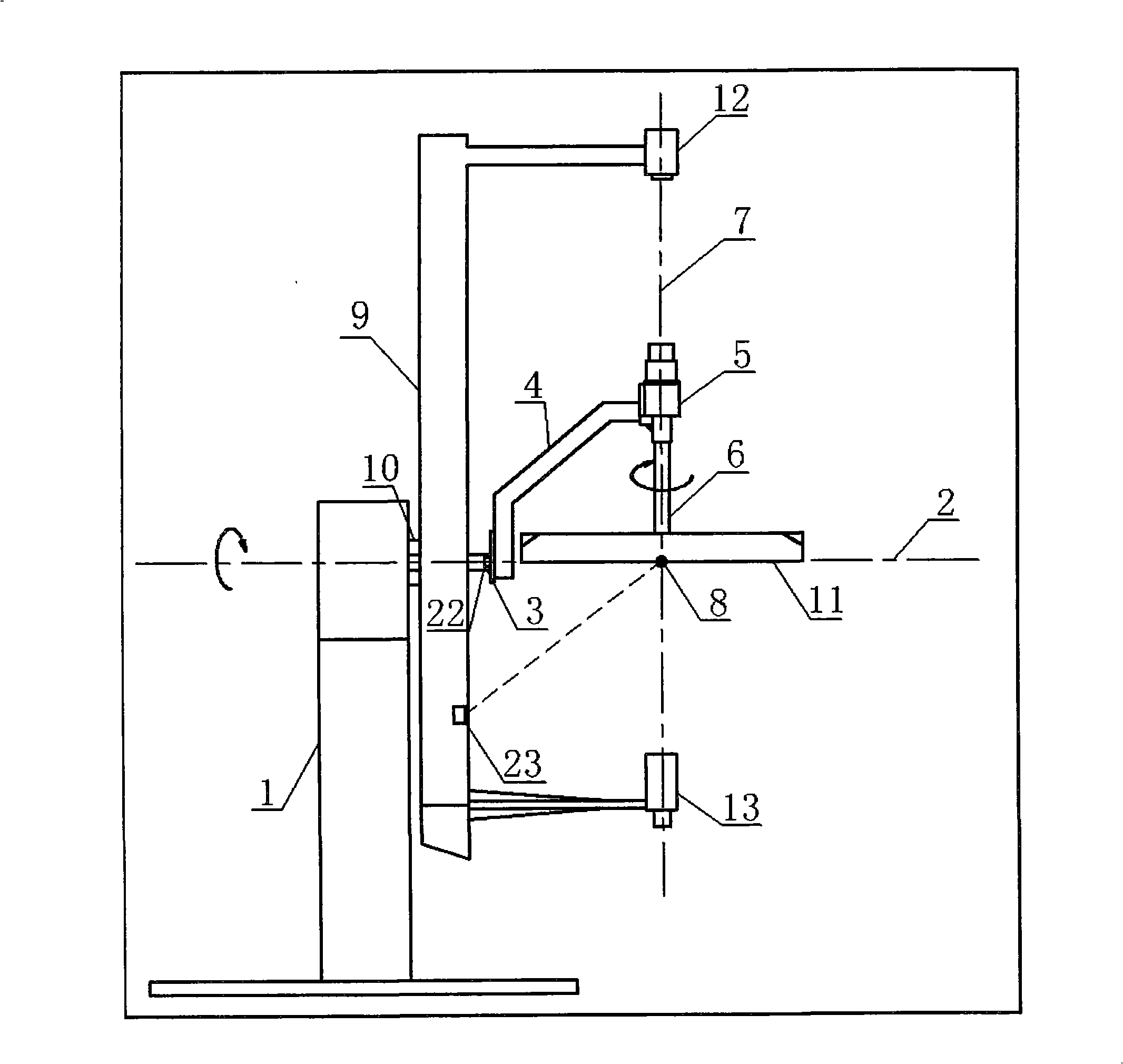
[0034] Such as figure 1 As shown in the schematic diagram of the scheme of Embodiment 1, one end of the rotating arm 9 is provided with a first photometric probe 13, and the first photometric probe measures the light intensity distribution of the measured light source 11 through the inverse square relationship of illuminance, and the other end of the rotating arm is provided with an electronic camera device 12. The photosensitive surfaces of the first photometric probe 13 and the electronic camera device 12 both face the measured light source 11, and their optical axes are perpendicular to the horizontal rotation centerline 2 and intersect at the two-axis rotation center 8.

Embodiment 2

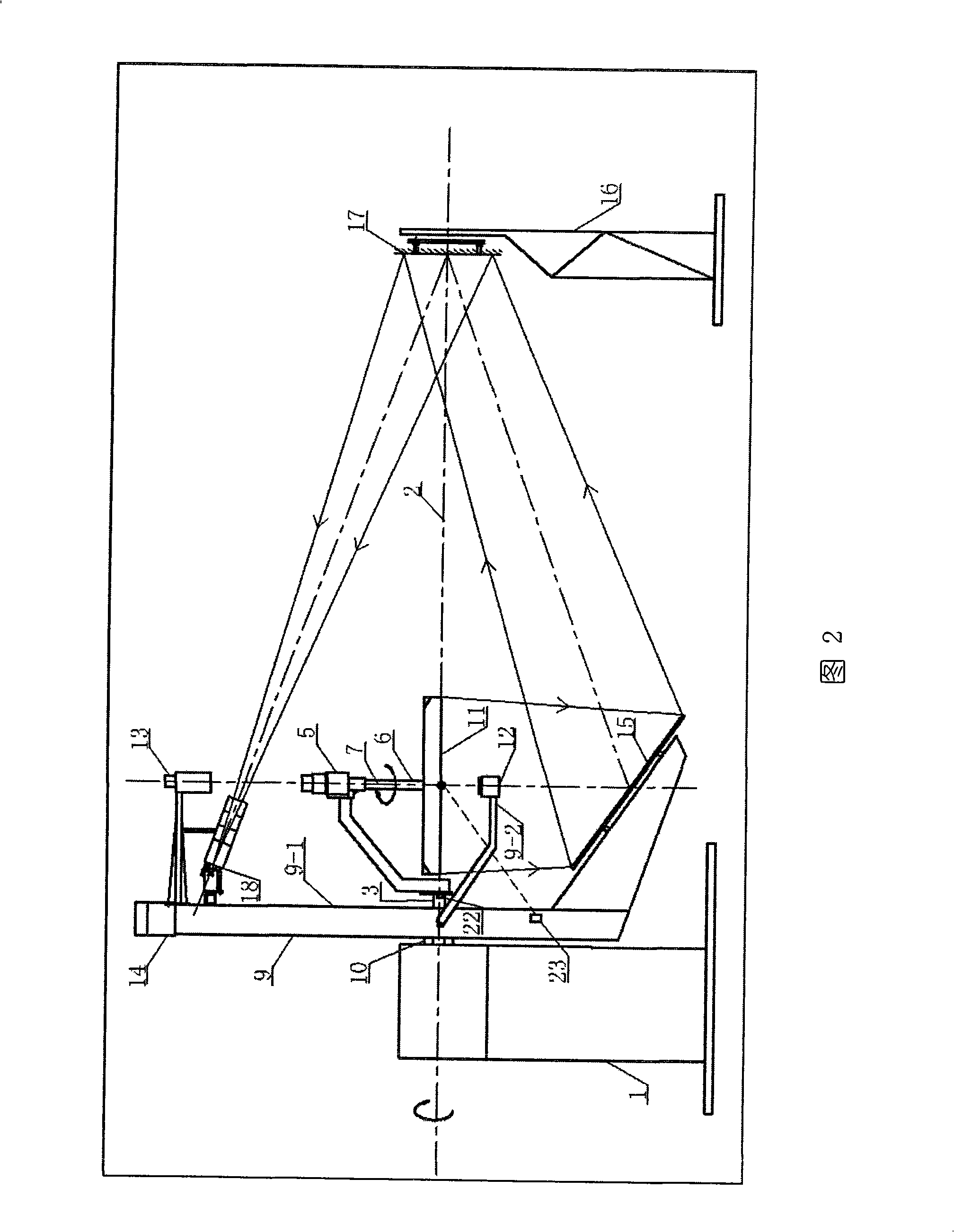
[0036] As shown in Figure 2, image 3 As shown in the schematic diagram of the scheme of embodiment 2, the pivoting arm 9 includes a pivoting arm trunk 9-1 and a pivoting arm secondary stem 9-2, and the two are arranged at a certain angle; one end of the pivoting arm trunk 9-1 is equipped with a rotating reflector 15, the other end is provided with the counterweight 14 of the rotating reflector 15, and the electronic camera device 12 is installed on one end of the secondary trunk 9-2 of the pivoting arm; the first photometric probe 13 is mounted on the counterweight of the pivoting arm trunk 9-1 At one end of the block 14, the light-receiving surfaces of the electronic camera device 12 and the first photometric probe 13 all face the light source 11 under test, and their optical axes are perpendicular to the horizontal rotation center line 2 and intersect at the two-axis rotation center 8 . On the opposite side of the base 1, a fixed reflector 17 is arranged. The fixed reflecto...

Embodiment 3

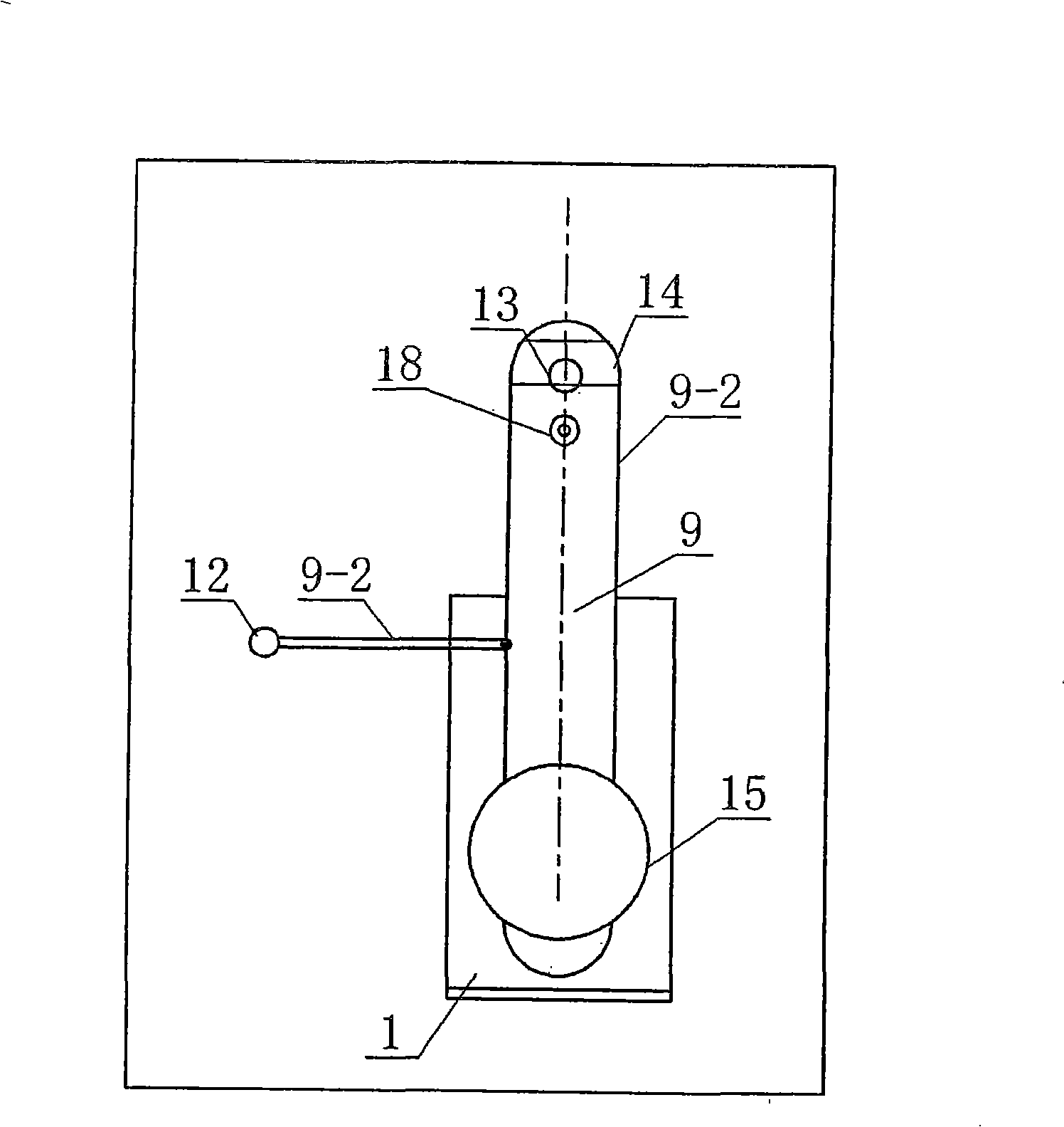
[0038] As shown in Figure 4, Figure 5 As shown in the schematic diagram of the scheme of embodiment 3, the rotating arm 9 includes a rotating arm trunk 9-1 and a rotating arm secondary trunk 9-2, and the two are arranged at a certain angle; one end of the rotating arm trunk 9-1 is equipped with a rotating reflector 15, the other end is provided with the counterweight 14 of the rotating mirror 15, and the electronic camera device 12 is installed on one end of the rotating arm secondary stem 9-2, and the electronic camera device 12 faces the measured light source 11, and its optical axis is in line with the horizontal The rotation center line 2 perpendicularly intersects the two-axis rotation center 8; the first photometric probe 13 is installed on one end of the counterweight 14 on the pivot arm trunk 9-1, the light-receiving surface of the first photometric probe faces the measured light source 11, and the second The optical axis of a photometric probe 13 perpendicularly inte...


PUM


Abstract

The invention discloses a distribution photometer, comprising a base; the base is coaxially provided with a horizontal rotation central line and a fixed axle, one end of a light arm is connected with the fixed axle, the other end thereof is connected with the measured light source by a rotation drive device, a rotation shaft which can rotate surrounding the horizontal rotation central line is rigidly connected with a rotation arm, an electronic image pick-up device is arranged on the rotation arm and directly faces to the measured light source, the light shaft of the electronic image pick-up device is vertical to the rotation central line and passes through the lightness center of the measured light source, and a lightness probe is arranged on the rotation arm or a bracket at the opposite side of the base. In the invention, when the electronic image pick-up device is taken as the image lightness measuring device, all the lightness indexes including the glare value and the like of the light source or lamps can be examined comprehensively and accurately by combining the lightness probe, so as to provide the comprehensive, reliable and visualized data and image for the examination of the light source or the lamps and for the lighting design.

Description

technical field [0001] The invention relates to a light and radiation measuring instrument, which is mainly used for measuring the light intensity distribution and brightness distribution of various light sources and lamps in all directions. Background technique [0002] A goniophotometer is an instrument that accurately measures the luminosity distribution of light sources and lamps with angle. The photometric detector in the existing goniophotometer generally adopts the illuminance detector, and according to the illuminance value detected by the illuminance meter in a certain direction, the light intensity value in the direction is calculated by using the inverse square relationship of the illuminance. Using the spatial light intensity distribution, data such as light distribution curves of light sources or lamps can be calculated accordingly to evaluate the quality of light sources or lamps or to design lighting. However, this method is used to examine the light intensit...

Claims


Application Information

Patent Timeline
Patent Type & Authority Applications(China)
IPC IPC(8): G01J1/02G01J1/04G01J1/52G01M11/00G01M11/02
Inventor 潘建根
Owner HANGZHOU EVERFINE PHOTO E INFO
Why Eureka
Try Eureka