Lens shifting mechanism with shape memory alloy

A memory alloy and lens technology, applied in the field of auto-focus lens modules, can solve problems such as insufficient simplification, unfavorable mass production, and reduced magnetic force

Inactive Publication Date: 2009-04-15
E PIN OPTICAL IND
View PDF21 Cites 39 Cited by
  • Summary
  • Abstract
  • Description
  • Claims
  • Application Information

AI Technical Summary

Problems solved by technology

[0003] Common designs of existing lens shifting mechanisms include: a piezoelectric motor (piezoelectric motor), which is formed using the principle of piezoelectric (piezoelectric) materials, but generally used piezoelectric materials cannot withstand reflow ( reflow) high temperature, and the special piezoelectric material that can withstand the high temperature of reflow is quite expensive; another kind is called voice coil motor (voice coil motor, referred to as VCM), which uses electromagnetic force and elastic parts (such as springs or shrapnel) ) are formed together, but the voice coil motor will be damaged or the magnetic force will be reduced at the reflow temperature. Therefore, the above-mentioned existing piezoelectric motors and voice coil motors cannot use reflow during assembly, resulting in mass production efficiency. Restricted; another form of shape memory alloy (SMA for short), which uses an SMA device (SMA device), and drives the lens to move through the "heat shrink and cold expand" characteristics of SMA Bit effect, because SMA can reach 5% shrinkage, which is far greater than the thermal expansion and contraction of general materials, and SMA can withstand high temperature reflow, so that reflow can be used during assembly, so the assembly output can be increased and there is a specific Practical value
At present, there are many existing technologies using SMA in the design field of lens shifting mechanism, such as: US5,185,621A, US5,279,123A, US5,459,544A, US6,307,678B2, US6,449,434B1, WO2005001540 、US20020136548、US2007058070、US2007047938、JP64000938、JP9127398、JP62067738、JP3196781、JP2006329111、JP2005275270、JP2005195998、JP2005156892、JP2004184775、JP2004129950、JP2004069986、JP2004038058、JP2000056208等,而上述各专利案虽然都是利用SMA作为镜头移位的驱动 However, the disclosed technical means or driving methods are different; however, most of the structures of the above-mentioned prior art are still relatively complex, and the volume is relatively large, which does not meet the miniaturization requirements of the lens module, such as US6,449,434B1 , which is to use an SMA wire to fix its two opposite ends and ma

Method used


Image

  • Lens shifting mechanism with shape memory alloy
  • Lens shifting mechanism with shape memory alloy
  • Lens shifting mechanism with shape memory alloy

Examples


no. 1 example

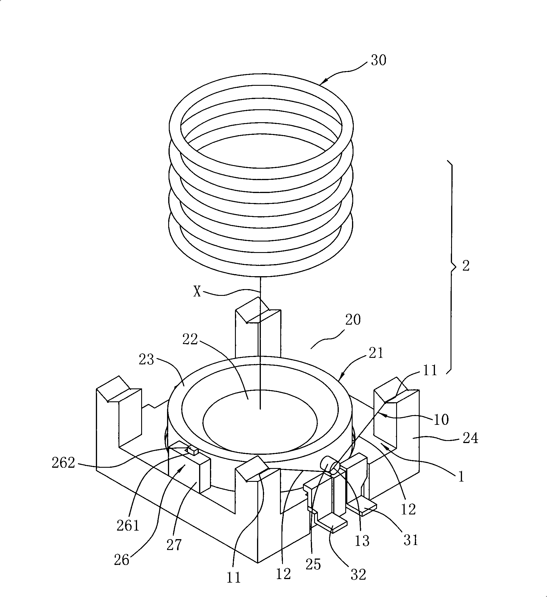
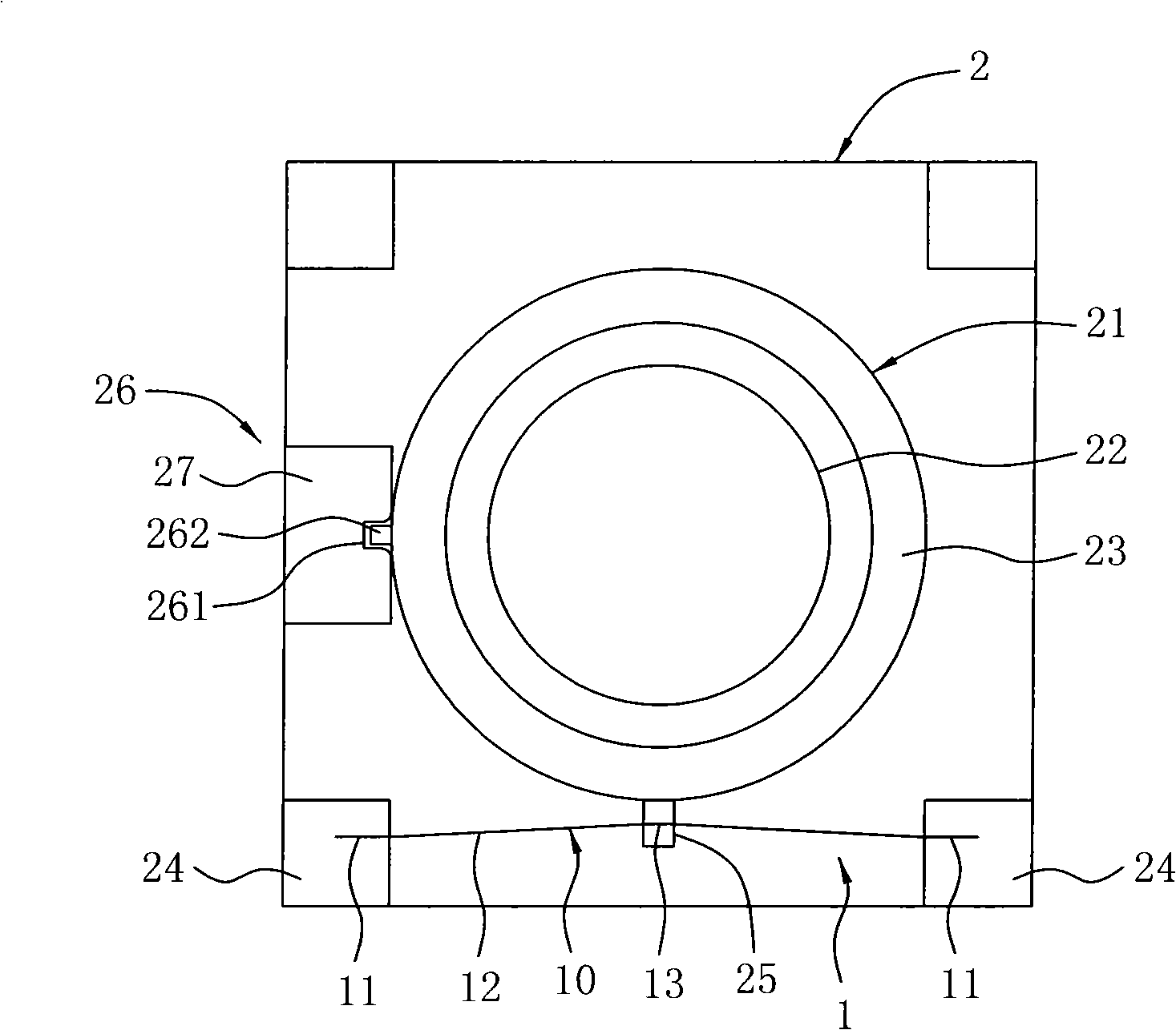
[0025] refer to Figure 1-3 As shown, the present embodiment utilizes an SMA wire 10. When the object distance is from far to near, the lens 21 moves away from the imaging side toward the object side to achieve the purpose of focusing; in this embodiment, the lens 21 and the imaging surface The distance changes are shown in Table 1:

[0026] Table I

[0027] Object distance(mm)

70

100

600

1000

infinity

camera shift

Distance (mm)

0.243

0.167

0.023

0.011

0

[0028] When focusing, the lens 21 is controlled to move, that is, the auto-focus lens 21 is controlled by a focus button (not shown in the figure), when the user presses the focus button, the electrodes 31, 32 can pass When the power is supplied to the lens shifting mechanism 1, when the control current flows through the SMA wire 10, Joule heat (Joule heat) may be generated due to the impedance of the SMA wire 10, causing ...

no. 2 example

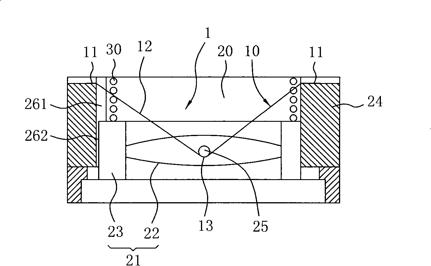
[0036] refer to Figure 4-6 As shown, the present embodiment utilizes two SMA wires 10, and the two SMA wires 10 are arranged at the outer periphery of the lens 21 symmetrically or equidistantly; the two SMA wires 10 of the present embodiment Its two opposite ends 11 are fixed on the two symmetrical sides of the outer edge of the lens 21, and each middle movable section 12 is respectively tensioned and suspended on the symmetrical sides respectively arranged on the outer edge of the lens 21 with its length to the middle point 13. On the hook 25 of each SMA wire 10, the middle movable section 12 of each SMA wire 10 forms a tense state with respect to the two opposite ends 11; through the above structure, when the two SMA wires 10 are heated due to current conduction, the middle of each SMA wire 10 The movable section 12 can be contracted synchronously and pull the corresponding hook 25 on the lens 21 to synchronously drive the lens 21 to slide and shift on the optical axis X to...

no. 3 example

[0042] refer to Figure 7-Figure 9 As shown, the present embodiment utilizes four SMA wires 10, and it is better that the four SMA wires 10 are arranged symmetrically or equidistantly around the outer periphery of the lens 21, that is, the two opposite ends of the four SMA wires 10 11 is respectively fixed on the four opposite sides of the lens 21, so that the middle movable section 12 of each SMA line 10 is respectively tensioned to the middle point 13 by its length and hung on the corresponding hook 25 set up on the opposite side of the outer edge of the lens 21 Above, the middle movable section 12 of each SMA wire 10 forms a tense state relative to the two opposite ends 11; through the above structure, when the four SMA wires 10 are heated due to current conduction, the middle movable section 12 of each SMA wire 10 can be synchronized Shrink and pull the corresponding hook 25 on the lens 21 to synchronously drive the lens 21 to slide and shift on the optical axis X to achie...


PUM


Abstract

The invention discloses a lens shifting mechanism with a shape memory alloy (SMA), and the lens shifting mechanism is suitable for an auto-focusing lens module. The SMA wire has two opposite ends and a middle moving segment between the two opposite ends, wherein, the two opposite ends are fixed, and the length direction middle point of the middle moving segment is tightened and suspended at a corresponding hook arranged at the outer edge of a lens retaining part, which causes the middle moving segment to form a stress state relative to the two opposite ends; when the SMA is heated, the middle moving segment can be retracted to pull the corresponding hook at the lens to drive the lens to shift by sliding to achieve auto-focusing effect; an elastic restoring piece can be further arranged at the lens retaining part, and when the SMA contracts to recover the original length due to cooling, the elastic restoring piece can supply restoring force to cause the lens to be restored to the original position; and a correspondingly matched guide rail device can be further arranged between the lens retaining part and an accommodation chamber to cause a lens set to steadily shift in the accommodation chamber by sliding.

Description

technical field [0001] The present invention relates to a lens displacement mechanism, especially a lens displacement mechanism controlled by a shape memory alloy wire (SMA wire) and a spring force for automatic focusing. In an autofocus lens module. Background technique [0002] Currently used digital cameras, mobile phones with shooting functions, notebook computers and other hand-held electronic devices often have a compact camera module (CCM for short) capable of auto-focusing (AF for short). , and the lens module basically includes: a cavity (housing); a lens composed of a lens group (lens group) and a lens holder (lens holder), which is sleeved in the cavity inside and on the optical axis, and can be displaced by sliding or screwing in the direction of approaching the object; and a lens displacement (control) mechanism (lensdisplacement / control mechanism), mainly used to drive the The lens produces a sliding or helical shifting movement on the optical axis to achieve...

Claims


Application Information

Patent Timeline
IPC IPC(8): G02B7/08G02B7/09G03B13/36
Inventor 徐三伟黄志雄吴诗斌
Owner E PIN OPTICAL IND
Why Eureka
Try Eureka