Cam follower device
A technology of cams and camshafts, which is applied to valve devices, engine components, machines/engines, etc., and can solve the problems of valve mechanism size increase, high friction, and high cost
- Summary
- Abstract
- Description
- Claims
- Application Information
AI Technical Summary
Problems solved by technology
Method used
Image
Examples
no. 1 example
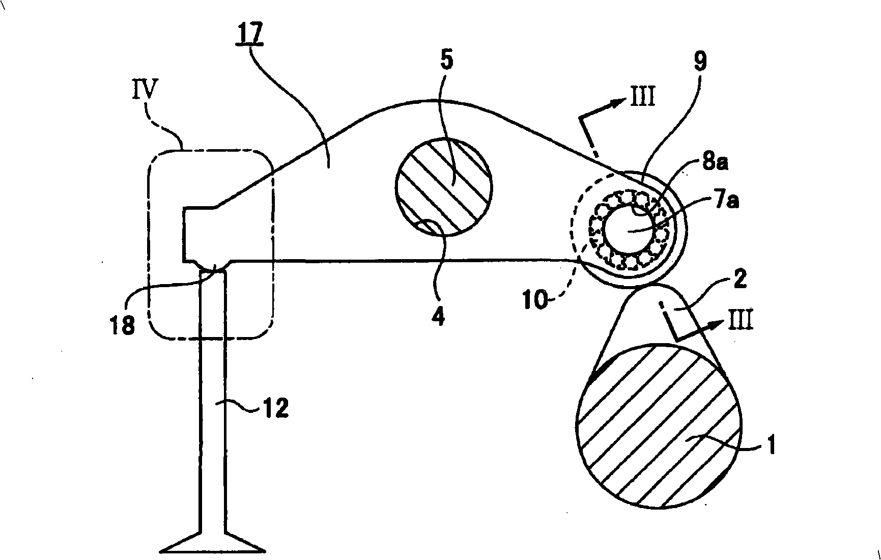
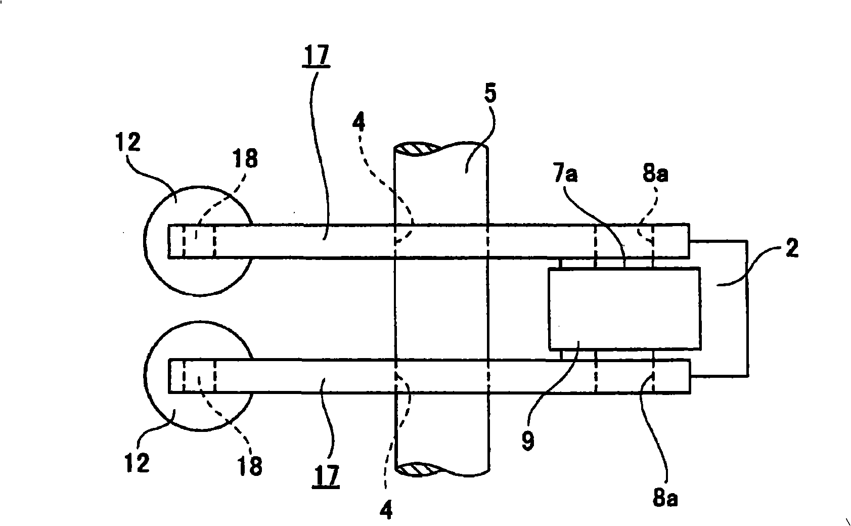
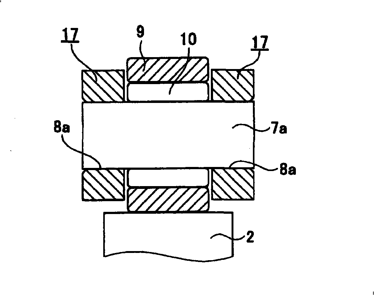
[0109] Figure 1 to Figure 4 A first embodiment of the invention is shown. The cam follower of this embodiment is configured for use in a valve train of an engine (OHC or DOHC type), such as a three-valve engine, a four-valve engine, or a five-valve engine, in which , the number of at least one of the intake valve and the exhaust valve provided for each cylinder is manufactured to be two or more. The cam follower device of the present embodiment thus designed includes a pair of plate-shaped rocker arms 17, 17, a support shaft 7a, and a tappet roller 9 that are identical in shape and size to each other.
[0110] Among these constituent parts, plate-like rocker arms 17 , 17 pairs are each formed into a shape like a boomerang by applying press working to a metal plate such as a steel plate. The two thus formed rocker arms 17 , 17 are arranged parallel to each other with a predetermined interval defined between the two rocker arms 17 , 17 . Furthermore, the support shaft 7a is ...
no. 2 example
[0125] Next, Figure 10 to Figure 11 A second embodiment of the invention is shown. In this embodiment, in order to provide the other end portion of the pair of rocker arms 17h, 17h (in Figure 10 To increase the strength at the middle left end portion), the two end portions are manufactured as thick portions 31, 31, and the protruding portions 18, 18 are provided on the other end portion. In this embodiment, in order to form the two thick portions 31, 31, the inner surfaces of the other end portions of the two rocker arms 17h, 17h are enlarged. Therefore, the thickness dimension T of the other end portion (thick portion 31, 31) of the two rocker arms 17h, 17h is made larger than the thickness dimension t of the one end portion and the middle portion of the two rocker arms 17h, 17h. (T>t). In the present embodiment constructed in the manner described above, compared to the two rocker arms 17h, the thickness dimension of 17h increases along its entire length without requirin...
no. 3 example
[0127] Next, Figure 12 A third embodiment of the invention is shown. Also, in this embodiment, in order to provide the other end portion of the pair of rocker arms 17i, 17i (in Figure 12 In order to increase the strength at the center left end portion), two of said other end portions are manufactured as thick portions 31a, 31a on which the protruding portions 18, 18 are provided. However, in the case of the present embodiment, in order to form the two thick portions 31a, 31a, the both side surfaces of the other end portions of the two rocker arms 17i, 17i are enlarged. Other configurations and functions of this embodiment are similar to those of the second embodiment described above.
PUM
 Abstract
Description
Claims
Application Information
 - R&D Engineer
- R&D Manager
- IP Professional
- Industry Leading Data Capabilities
- Powerful AI technology
- Patent DNA Extraction
Browse by: Latest US Patents, China's latest patents, Technical Efficacy Thesaurus, Application Domain, Technology Topic, Popular Technical Reports.
© 2024 PatSnap. All rights reserved.Legal|Privacy policy|Modern Slavery Act Transparency Statement|Sitemap|About US| Contact US: help@patsnap.com


