Control method of large-sized mining grinding mill end flange welding deformation

A control method and flange welding technology, applied in welding equipment, welding equipment, auxiliary welding equipment, etc., can solve the problem of increasing the lateral shrinkage force of the outer weld metal, the flange hook at the end of the welding sequence is incorrect, and the welder's non-existence. Correct welding and other issues can shorten the production cycle, reduce production costs, and reduce welding deformation.

Inactive Publication Date: 2009-04-22
CITIC HEAVY INDUSTRIES CO LTD
View PDF0 Cites 26 Cited by
  • Summary
  • Abstract
  • Description
  • Claims
  • Application Information

AI Technical Summary

Problems solved by technology

[0006] 2. Due to the longitudinal shrinkage of the weld between the end flange and the cylinder, but the end flange itself does not shrink, the circumference of the inner circle at the weld is smaller than the circumference of the inner circle at the end of the end flange, resulting in a waist, forcing The hook of the end flange is turned outward, which is the main reason for the deformation of the hook
[0007] 3. Welding groove problem: the groove form of the cylinder body and the end flange is mostly large on the outside and small on the inside, which increases the lateral shrinkage force of the outer weld metal and intensifies the occurrence of the hook of the end flange
[0008] 4. Incorrect welding by the welder, that is, the incorrect welding sequence also leads to the occurrence of end flange hooks

Method used


Image

  • Control method of large-sized mining grinding mill end flange welding deformation
  • Control method of large-sized mining grinding mill end flange welding deformation
  • Control method of large-sized mining grinding mill end flange welding deformation

Examples


Embodiment Construction

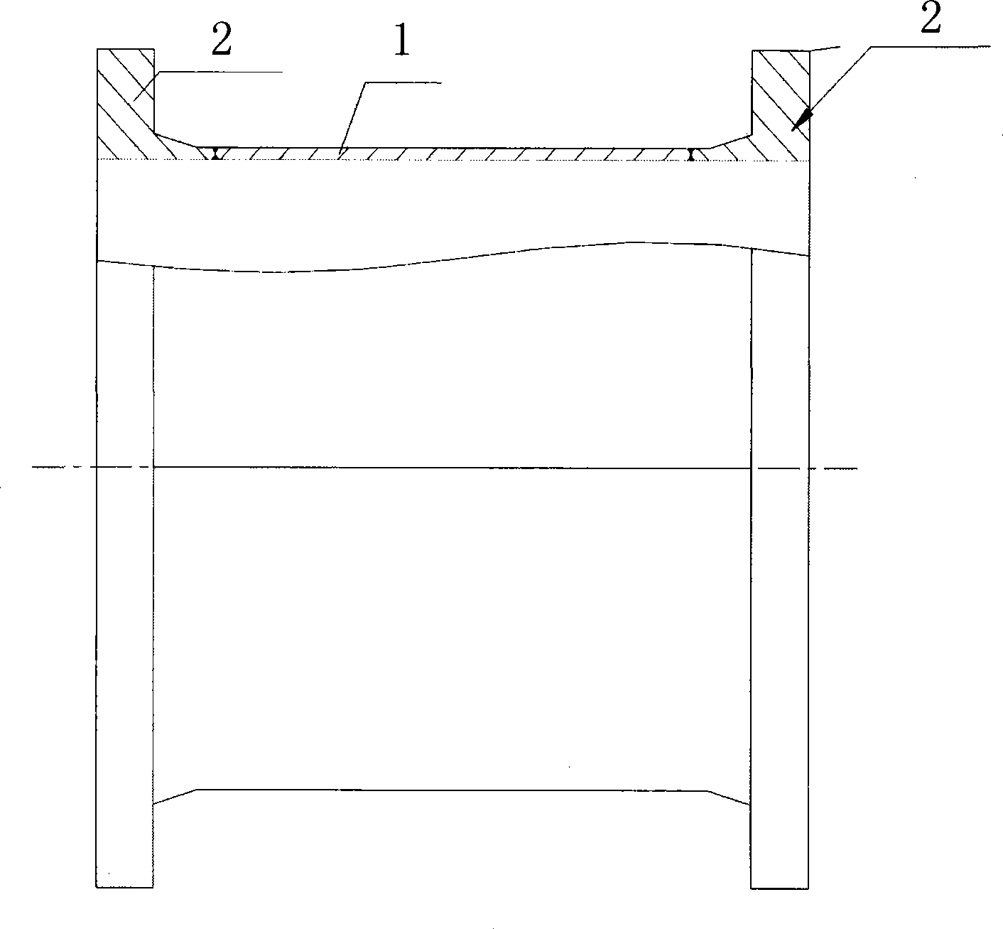
[0037] Take φ8.8×4.8m semi-autogenous mill end flange welding as an example. The technical parameters of the mill are: outer dimension φ9300×4800mm, end flange outer diameter 9300mm, inner diameter 8800mm, cylinder thickness 60mm, material Q235D.

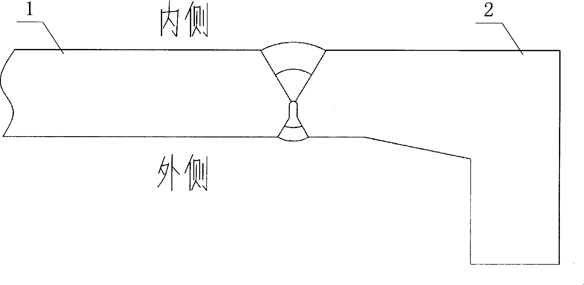
[0038] Groove butt joint method is handled according to the equation of internal and external equality, relevant parameters see Figure 7 , the specific control method is as follows:

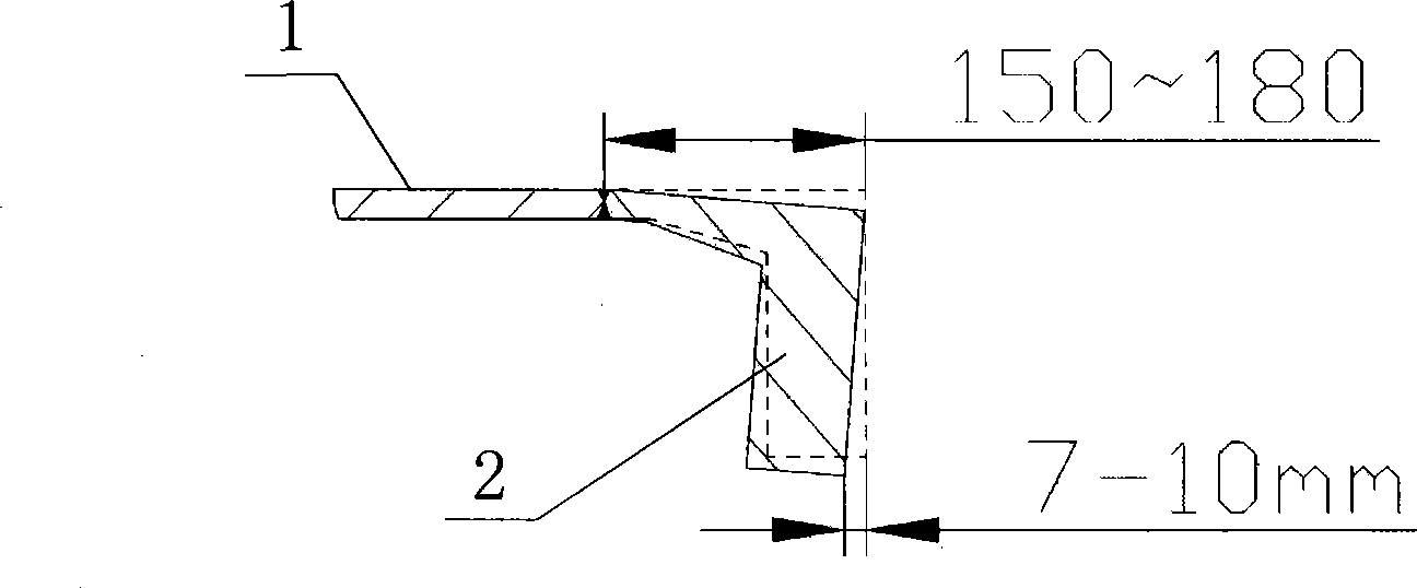
[0039] 1. Use the welding rod J502 φ5 welding rod for spot welding at intervals of 500mm between the cylinder body and the end flange. The spot welding length is about 30mm. And the connecting plate is used to connect the cylinder section and the end flange on the inner side of the cylinder body.

[0040] 2. Hang the cylinder on the welding roller, heat the connection between the cylinder and the end flange to 100-150°C with gas, select HO8A, Φ4mm welding wire, use the manipulator to use submerged arc welding, and use multiple welding methods during...


PUM


Abstract

The invention provides a method for controlling welding deformation of an end flange of a large-sized mine mill, which comprises two contents: 1. the groove butt joint mode and welding mode before the end flange(2) and a barrel body(1) are welded are improved, the groove butt joint mode has three types which are small inner part and big outer part type, equal inner part and outer part type and big inner part and small outer part type respectively, and the welding mode correspondingly has three types; and 2. the correction is performed after welding, which has obvious effect, and the product quality is effectively ensured. By utilizing one welding stress to overcome the other welding stress, the welding stresses inside and outside the connecting part between the barrel body and the flange are balanced (i.e. the transverse shrinkages of the welding seams are the same); in the end, when the barrel body of the mill is subjected to relief annealing, the welding stresses inside and outside the barrel body of the mill are equally released, so that the method has the advantages of having little welding deformation, reducing the work load of correction after welding, improving the production efficiency, shortening the production cycle and lowering the production cost.

Description

technical field [0001] The invention belongs to the field of welding technology, and in particular relates to a method for controlling the welding deformation of a large mining mill end flange. Background technique [0002] The history of research and development and manufacturing of CITIC Heavy Industry mining mills began in the mid-1980s and entered the late 1990s. Large-scale domestic mining mills have become a trend of technological development. The main structure of the mining mill cylinder is as follows figure 1 shown. [0003] The welding deformation between the cylinder body and the flanges at both ends has always plagued product quality, production progress and product delivery time. The welding deformation of the end flange is also called the hook deformation. Its specific meaning means that the actual measurement value of the outer circle length direction of the two flange end faces is 15-20mm smaller than the actual measurement value of the inner circle length d...

Claims


Application Information

Patent Timeline
Patent Type & Authority Applications(China)
IPC IPC(8): B23K31/02B23K33/00B23K9/18B23K9/235B23K9/095B23K37/00
Inventor 段世新曹林
Owner CITIC HEAVY INDUSTRIES CO LTD
Why Eureka
Try Eureka