Heat radiation structure of LED lamp backlight device

A technology for LED lamps and backlight devices, which is applied to cooling/heating devices of lighting devices, lighting devices, semiconductor devices of light-emitting elements, etc., can solve the problem of no LED lamp backlight devices.

Inactive Publication Date: 2009-04-22
NANJING NEW LANDMORE DISPLAY TECH
View PDF0 Cites 9 Cited by
  • Summary
  • Abstract
  • Description
  • Claims
  • Application Information

AI Technical Summary

Problems solved by technology

However, there is no heat dissipation device or structure for dissipating heat from the LED backlight device in the market at present.

Method used


Image

  • Heat radiation structure of LED lamp backlight device
  • Heat radiation structure of LED lamp backlight device
  • Heat radiation structure of LED lamp backlight device

Examples


Embodiment 1

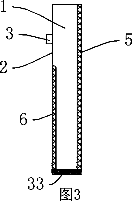
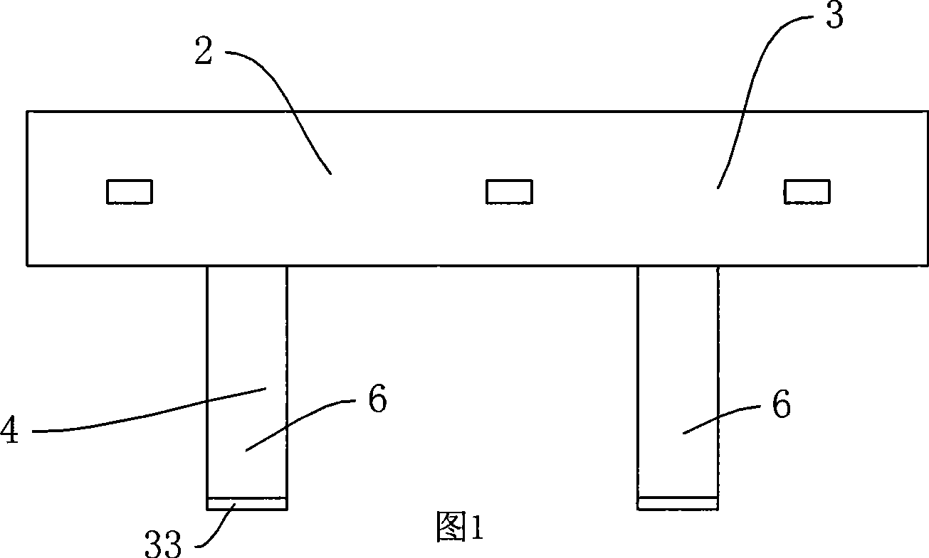
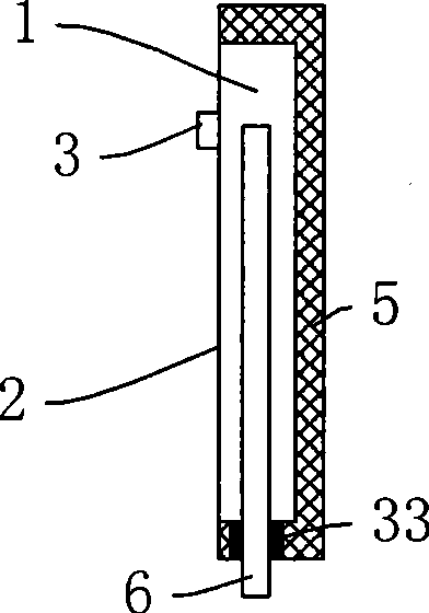
[0026] As shown in Figure 1-3, the led light backlight device includes a light bar 1, three led lights 3 are arranged on the left end surface 2 of the light bar 1, and two connecting parts protruding from the lower side of the light bar are arranged on the lower side of the light bar 1 4. The heat conduction layer 5 is connected to the right end surface of the light bar and the right end surface of the connecting part, and the positive and negative pins 6 are respectively arranged on the positive and negative pins 6 on the left end surfaces of the two connecting parts 4 . The material of the heat conduction layer is red copper. The silicone grease 33 at the lower end of the connection part 4 connects the positive and negative pins 6 with the heat conduction layer 5 . The heat on the positive and negative pins 6 mainly transfers heat to the heat conduction layer through the silicon grease and the light strip body in the form of heat conduction.

Embodiment 2

[0028] Referring to FIGS. 1-3, 7 and 8, the led lamp backlight device includes a light bar 1, a backlight board 30 and a printed circuit board 10 electrically connected to the led lamp (not shown). Three LED lamps 3 are arranged on the left end surface 2 of the light bar 1, and two connection parts 4 protruding from the lower side of the light bar are arranged on the lower side of the light bar 1, and are connected to the right end surface of the light bar and the heat conduction layer on the right end surface of the connection part 5. The positive and negative pins 6 are respectively arranged on the left end surfaces of the two connecting parts 4 .

[0029] The light bar is connected to the side 31 of the backlight board. A heat dissipation layer 32 for dissipating heat from the backlight is provided on the upper and lower end surfaces of the backlight close to the light bar.

[0030] The printed circuit board 10 includes a base material 11 , a copper clad layer 12 on the up...

Embodiment 3

[0037]As shown in Figure 4-6, the led light backlight device includes a light bar 1, three led lights 3 are arranged on the left end surface 2 of the light bar 1, and the heat conduction part is a heat conduction plate connected to the right end face, the upper side and the lower side of the light bar. Layer 5. The material of the heat conducting layer is copper. Positive and negative pins 6 are drawn out from the lower side. There is silicone grease 33 between the positive and negative pins 6 and the heat conduction layer. The heat on the positive and negative pins 6 mainly transfers heat to the heat conduction layer through the silicon grease and the light strip body in the form of heat conduction.


PUM


Abstract

The invention aims at providing a heat dissipation structure of an LED lamp backlight device, and an LED lamp which has the heat dissipation structure has the advantages of the prolonged service life, the improved luminous efficiency and the ensured imaging quality of a liquid-crystal display panel. In the heat dissipation structure of the LED lamp backlight device, the LED lamp backlight device comprises a lamp strip which is provided with at least one LED lamp as well as a positive pin and a negative pin that are used for supplying power for the LED lamp; the positive pin and the negative pin of the heat dissipation structure are connected with a heat conducting part by material which can conduct heat, but is insulative.

Description

technical field [0001] The invention relates to a heat dissipation structure of an LED lamp backlight device. technical background [0002] At present, the backlight sources of LCD TVs are mainly condenser lamps, and LCD TVs with LED lights as backlight sources have also begun to appear. There are two forms of led lights as backlight sources: side backlight (led lights are arranged on the side of the backlight board) and bottom backlight (led lights are arranged on the bottom surface of the backlight board). Compared with condensing lamps, LED lamps are energy-saving, have a long life, small size, and low temperature rise. They are regarded as the future development trend of LCD TVs. [0003] Nevertheless, when the LED backlight device is in use, there is still a phenomenon of temperature rise, especially near the LED lamp, the temperature rise is more obvious. The temperature rise not only reduces the luminous efficiency of the led, but also makes the temperature of the l...

Claims


Application Information

Patent Timeline
Patent Type & Authority Applications(China)
IPC IPC(8): F21V29/00H01L23/36G02F1/13357F21Y101/02F21V29/507F21V29/74F21V29/87F21Y115/10G02F1/1335
Inventor 应少炯魏贤国
Owner NANJING NEW LANDMORE DISPLAY TECH
Why Eureka
Try Eureka