Automatic charging and discharging and transmitting device for handstand type numerical controlled lathe

A technology of automatic loading and unloading, CNC lathes, applied in the field of CNC lathes, can solve the problems of the influence of weight on the clamping accuracy, many processing surfaces, and the incompetence of horizontal CNC lathes, etc., to achieve automatic factory production and reduce labor intensity. Effect

Active Publication Date: 2009-04-29
CSC BEARING
View PDF0 Cites 11 Cited by
  • Summary
  • Abstract
  • Description
  • Claims
  • Application Information

AI Technical Summary

Problems solved by technology

Most of the existing bearing processing equipment is a horizontal CNC lathe. However, when machining medium and large-sized bearing rings with a diameter of 100-400 mm, due to the limitation of the clamping accuracy and the radius of rotation of the lathe, the horizontal CNC lathe is very difficult. incompetent
Especially in the process of processing high-strength metal materials with a horizontal CNC lathe above Φ200mm, since the workpiece is installed vertically, the weight of the workpiece has a significant impact on the clamping accuracy, and its chip removal is easy to scratch the surface of the workpiece, plus It is more complicated to realize automatic loading and unloading, so the idea of ​​using an inverted CNC lathe to process medium and large-sized bea

Method used


Image

  • Automatic charging and discharging and transmitting device for handstand type numerical controlled lathe
  • Automatic charging and discharging and transmitting device for handstand type numerical controlled lathe
  • Automatic charging and discharging and transmitting device for handstand type numerical controlled lathe

Examples


Embodiment Construction

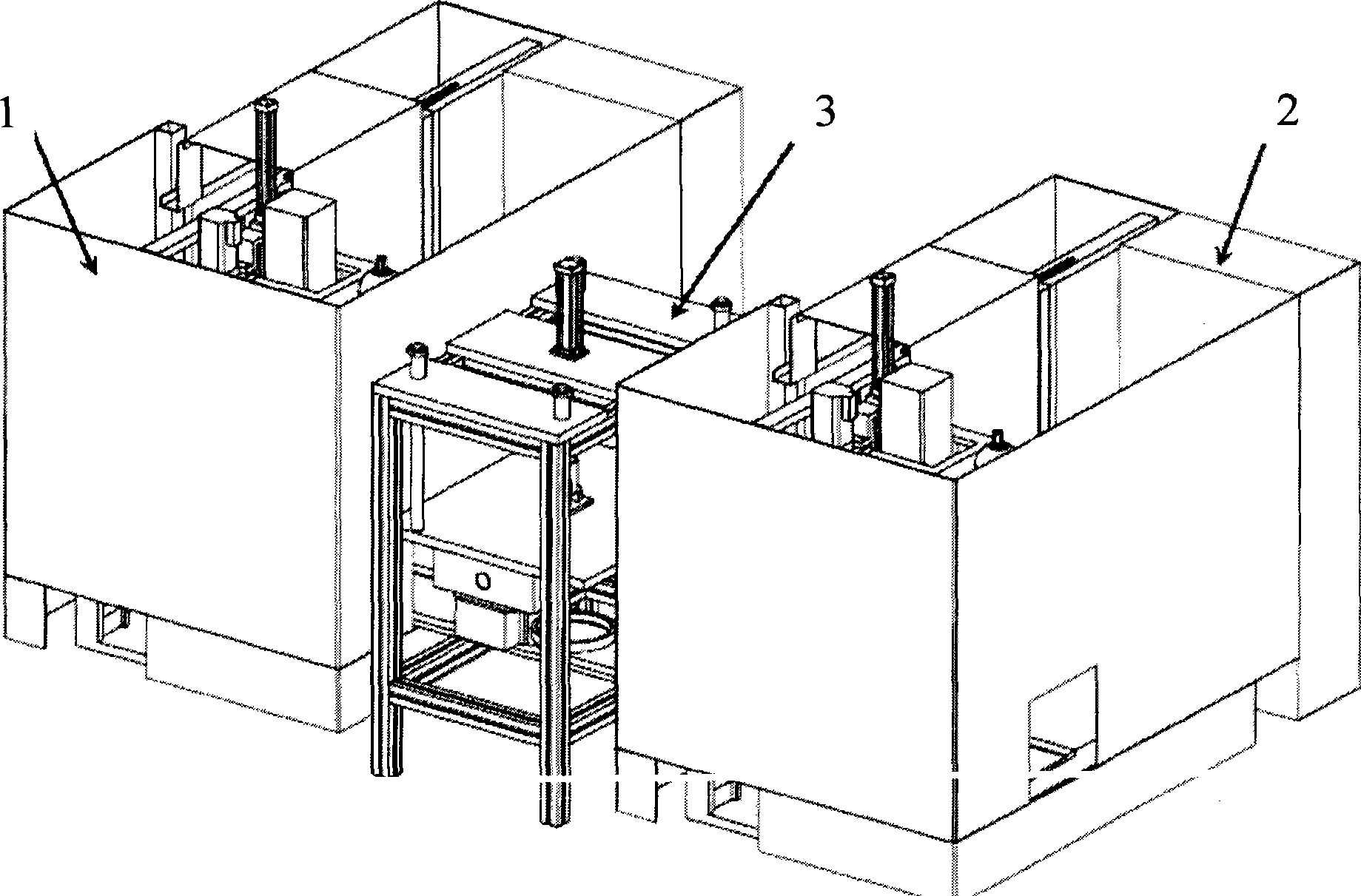
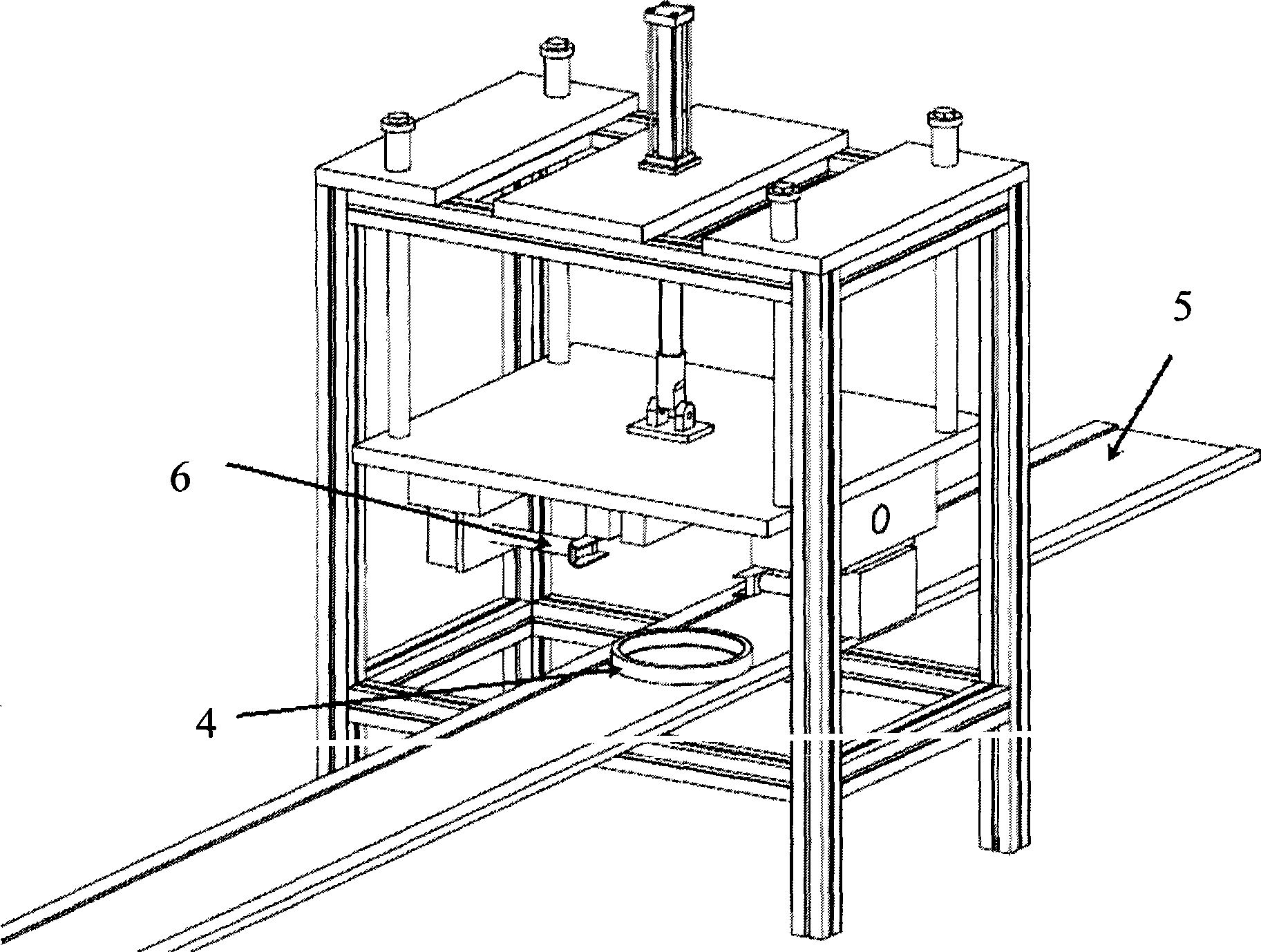
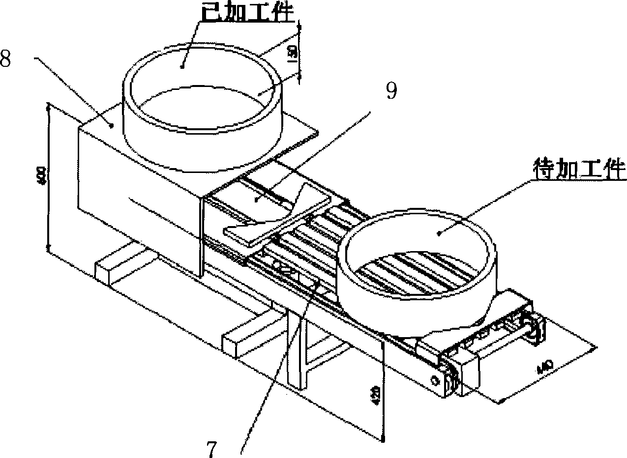
[0013] Figure 1-Figure 3 It is a schematic diagram of a specific embodiment of the present invention and the structure of each part thereof. The embodiments of the present invention will be described below with reference to the accompanying drawings.

[0014] Such as figure 1 As shown, the automatic loading and unloading and transmission device for inverted CNC lathes according to the present invention includes an loading and unloading platform, a conveying guide 5 and a workpiece turning mechanism 3. The loading and unloading platform is set on each inverted CNC lathe 1, 2 On one side of the bed, there is a conveying hole at the back of the bed. The conveying guide 5 is arranged from the conveying hole to the loading and unloading platform and the inverted CNC lathes 1 and 2 are connected to each other. The workpiece turning mechanism 3 is set in each inverted CNC. On the conveying guide rail 5 between the lathes 1 and 2. Such as figure 2 , The workpiece turning mechanism 3 is...


PUM


Abstract

The invention discloses an automatic feeding and discharging and transmission device used for an inverted numerically controlled lathe, comprising a feeding and discharging platform, a conveying guide rail and a workpiece turnover mechanism. The feeding and discharging platform is arranged at one side of the lathe bed of the lathe, the back of the lathe bed is provided with a feed hole, the conveying guide rail is distributed and arranged on the feeding and discharging platform from the feed hole and is connected with the subsequent inverted numerically controlled lathes mutually, and the workpiece turnover mechanism is arranged on the conveying guide rail among the lathes, wherein, the feeding and discharging platform comprises a conveying table, a discharging platform and an automatic aligning mechanism; the conveying table has fixed structure which is driven by a chain and connected with the conveying guide rail, the discharging platform is driven by the chain at the bottom to carry out reciprocating motion, and the automatic aligning mechanism is arranged between the conveying table and the discharging platform. In the invention, the workpiece feeding and discharging is realized by the automatic feeding and discharging and transmission device, thus effectively reducing the labor intensity of workers; and the workpiece machining process and the workpiece feeding and discharging can be finished on one machine, thus realizing the factory automated production.

Description

Technical field: [0001] The invention relates to the field of numerical control lathes, in particular to an automatic loading and unloading and transmission device used in a production line composed of multiple inverted numerical control lathes. Background technique: [0002] With the continuous development of equipment manufacturing technology, the demand for bearings from all walks of life is increasing, and its technical requirements are getting higher and higher, which makes the trend of general bearing specialization more and more obvious. The existing bearing processing equipment is mostly horizontal CNC lathes. However, due to the clamping accuracy and the limitation of the turning radius of the lathe, the horizontal CNC lathe has been very effective when machining medium and large bearing rings with a diameter of 100-400mm. Difficult. Especially when the horizontal CNC lathe is processing high-strength metal materials above Φ200mm, due to the vertical installation of the ...

Claims


Application Information

Patent Timeline
IPC IPC(8): B23B15/00B23B13/00
Inventor 章泳健毛仲武于学勇董强汪定华
Owner CSC BEARING
Why Eureka
Try Eureka