Sound deadening system for motorcycle

A technology for motorcycles and mufflers, applied in mufflers, engine components, machines/engines, etc., can solve problems such as burns, easy access, and potential safety hazards, and achieve a safe, versatile, and simple structure. Effect

Inactive Publication Date: 2009-04-29
力帆科技(集团)股份有限公司
View PDF0 Cites 3 Cited by
  • Summary
  • Abstract
  • Description
  • Claims
  • Application Information

AI Technical Summary

Problems solved by technology

Since the temperature of the exhaust gas generated by the engine operation is as high as 600-700°C, when the exhaust gas flows through the muffler 2, the heat of the high-temperature gas is directly transferred to the outer wall of the muffler 2, resulting in a high temperature of the outer wall of the muffler 2, about 300-300°C. 500°C, it is easy to cause burns, and there is a serious safety hazard; especially for off-road motorcycles, due to its own characteristics, the layout of the muffler is relatively high, close to the upper part of the car body, and the driver and passengers do not pay attention It is easy to touch the outer wall of the muffler 2, and the scalding accidents caused by this happen from time to time
[0003] Some motorcycles use the method of adding a protective plate to cover the muffler 2. Since the protective plate is a newly added part after the muffler is assembled on the motorcycle, the protective plate cannot completely cover the muffler 2 due to the limitation of the installation position. Covering, its protective effect is poor, while destroying the overall appearance of the motorcycle, the unshielded parts of the muffler 2 will still cause burns
In addition, a part of the protective plate is in contact with the outer wall of the muffler 2, resulting in a hot spot with a higher temperature on the protective plate, which is also easy to burn people

Method used


Image

  • Sound deadening system for motorcycle
  • Sound deadening system for motorcycle
  • Sound deadening system for motorcycle

Examples


Embodiment Construction

[0017] Below in conjunction with accompanying drawing and embodiment, the present invention will be further described:

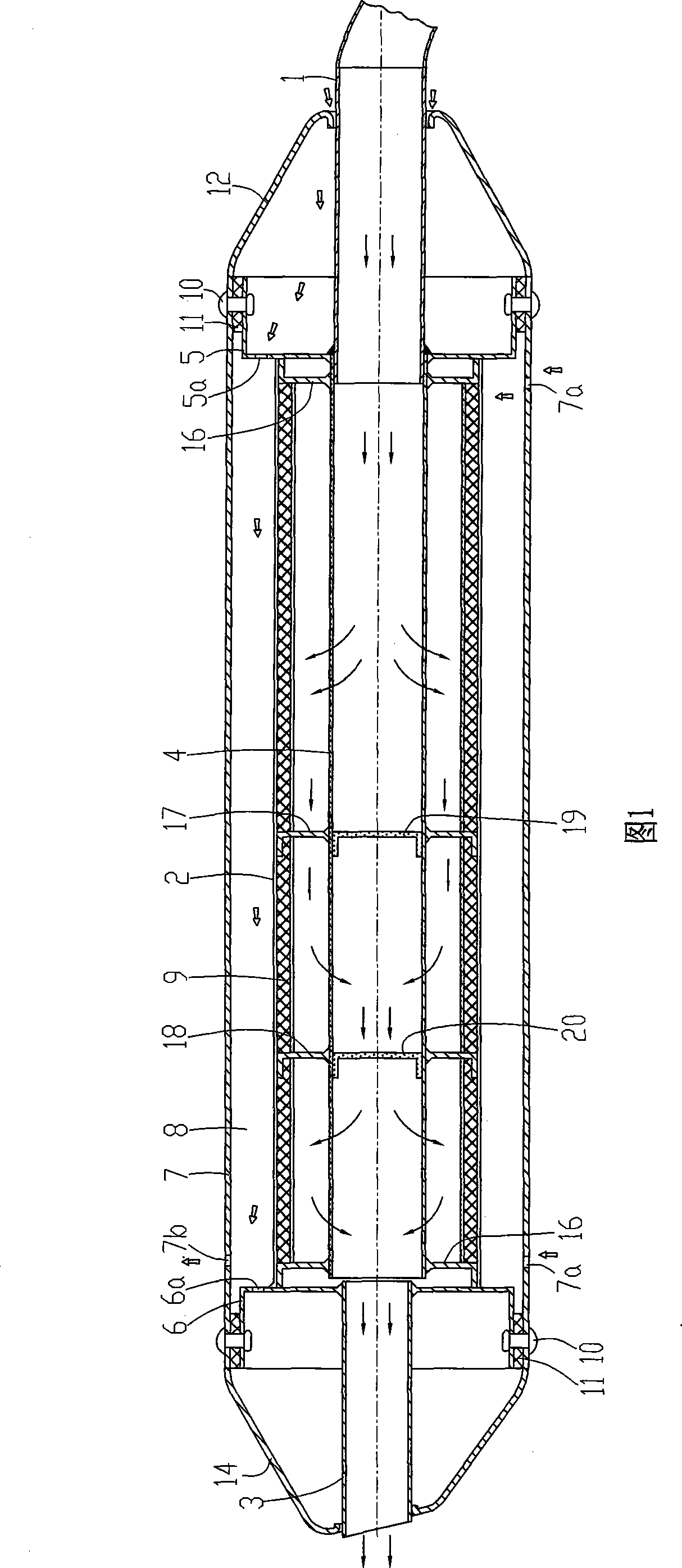
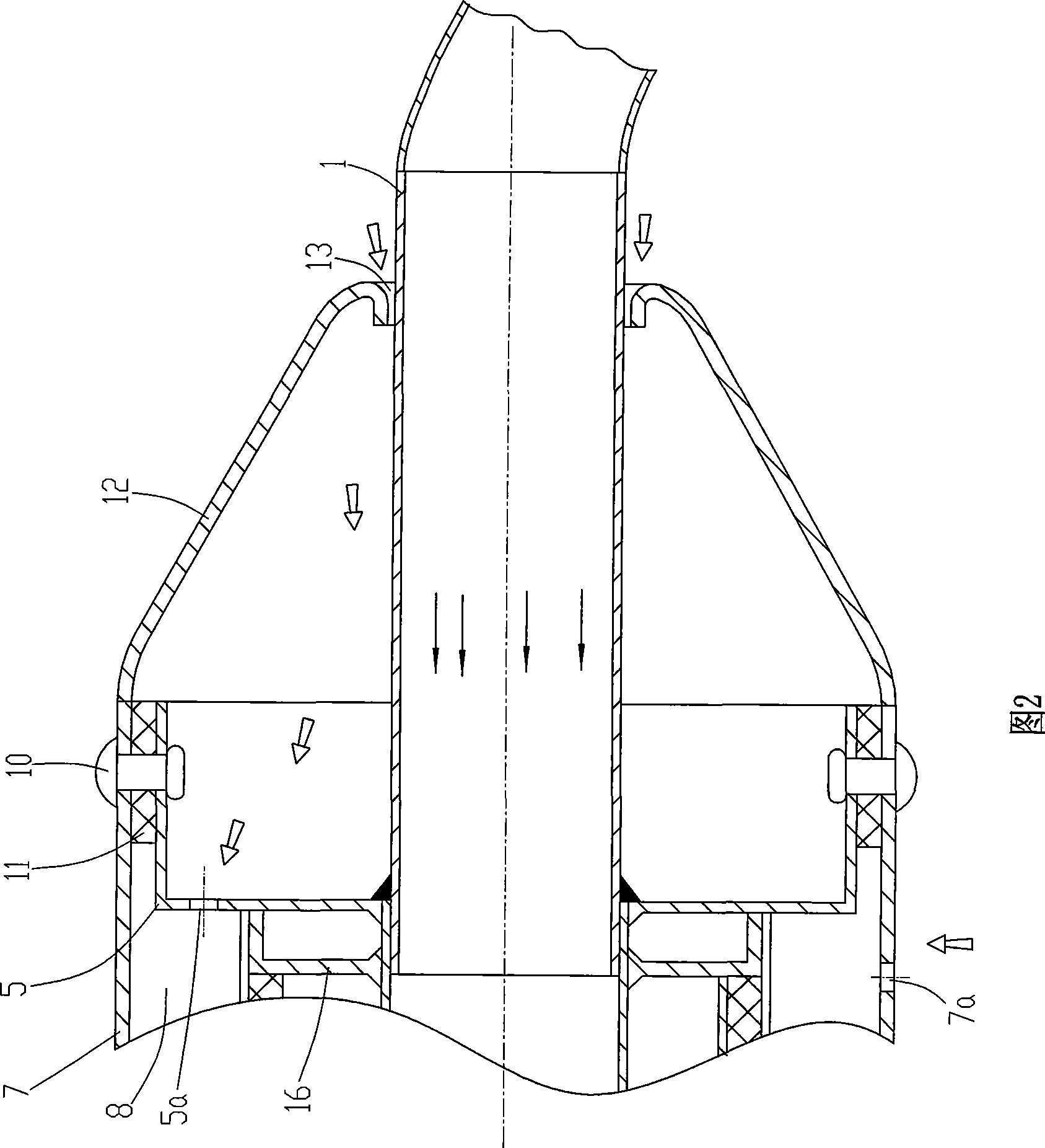
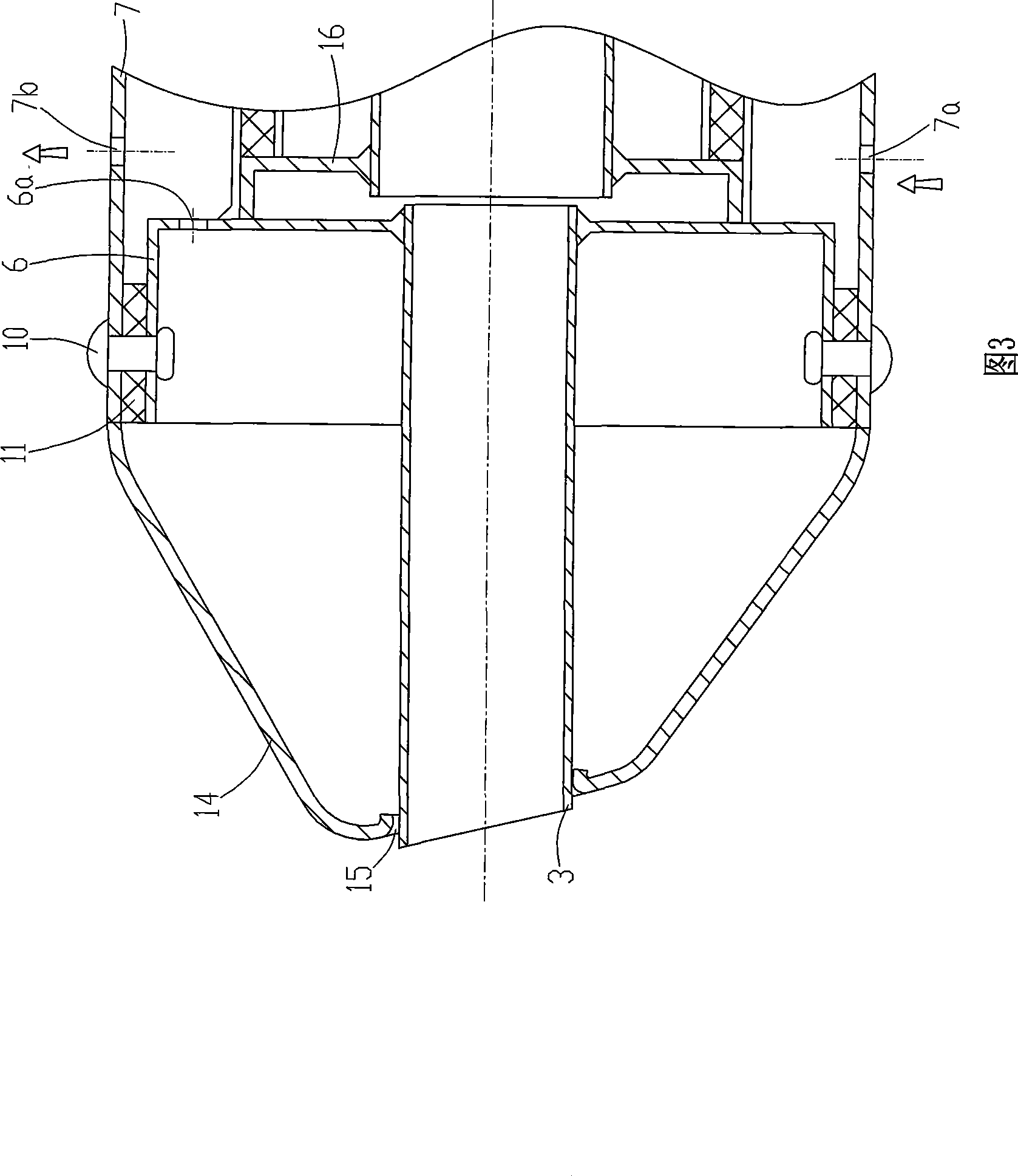
[0018] As shown in Figure 1, the present invention consists of an intake pipe 1, a muffler 2, a tail pipe 3, a muffler pipe 4, a front nipple 5, a rear nipple 6, an outer cylinder 7, a heat insulator 9, a front decorative cap 12 and The rear decorative cap 14 and other components are formed. The muffler 2 is a straight-through pipe structure, the wall of the muffler 2 is a sandwich structure, and the sandwich is filled with a heat insulating body 9, which can be made of heat insulating cotton or other equivalent heat insulating materials. A muffler tube 4 is arranged in the muffler 2, and the assembly method in the background technology can be used between the muffler tube 4 and the muffler 2 (see FIG. 4). The interior of the body 2 is divided into three chambers by two partition plates, and the two adjacent chambers are communicated through a muffler pipe ...


PUM


Abstract

Disclosed is a motorcycle noise reduction system. A noise reduction pipe is arranged in a noise abatement body, the front end of the noise abatement body is connected with an air inlet pipe through a front joint, and the rear end is connected with a tail pipe through a rear joint. The outside of the noise abatement body is provided with an outer cylinder, the front end and the rear end of the outer cylinder are respectively connected with the front and the rear joints, an annular air convection chamber is formed between the outer cylinder and the noise abatement body, and the air convection chamber is communicated with the outside through the air inlet on the bottom of the outer cylinder and the air outlet on the top surface of the outer cylinder. The invention adopts the mode combining heat insulation and natural air flow cooling, can control the surface temperature of the outer cylinder of the silencer at about 50 DEG C, which can prevent the person from being scalded even the person contacts the outer cylinder directly, thereby fundamentally eliminating the safety hidden trouble caused by high temperature of the outer wall of the silencer. The invention has the characteristics of simple structure, easy implementation, strong generality, and the like.

Description

technical field [0001] The invention belongs to the technical field of motorcycle noise reduction, in particular to a layered heat insulation type motorcycle noise reduction system. Background technique [0002] The structure of a traditional motorcycle muffler is shown in Figure 4. A muffler pipe 4 is arranged in the muffler 2, and the tail of the intake pipe 1 is fitted with a front sleeve 5, which is welded with the front end of the muffler 2; the tail pipe The front part of 3 is fitted with a rear socket 6 , which is welded with the rear end of the muffler 2 . The high-temperature exhaust gas discharged during the operation of the motorcycle engine enters the muffler 2 from the intake pipe 1 of the muffler, and is discharged from the tail pipe 3 after being muffled by the muffler pipe 4 . Since the temperature of the exhaust gas generated by the operation of the engine is as high as 600-700 °C, when the exhaust gas flows through the muffler 2, the heat of the high-tempe...

Claims


Application Information

Patent Timeline
Patent Type & Authority Applications(China)
IPC IPC(8): F01N7/08F01N7/14F01N13/08F01N13/14
Inventor 夏先明
Owner 力帆科技(集团)股份有限公司
Why Eureka
Try Eureka