Multi-vane cycling air blowing and sucking flow control method for aviation turbofan engine compression system

A turbofan engine and compression system technology, applied in the direction of machines/engines, pump control, mechanical equipment, etc., can solve difficult recycling, affect the life and reliability of high-load fan/compressor blades, reduce the thrust of the whole machine, etc. problem, to achieve the effect of solving the problem of recycling, avoiding the increase of weight and avoiding the increase of failure

Inactive Publication Date: 2009-04-29
BEIHANG UNIV
View PDF0 Cites 10 Cited by
  • Summary
  • Abstract
  • Description
  • Claims
  • Application Information

AI Technical Summary

Problems solved by technology

[0006] To sum up, in the aviation turbofan engine compression system, the existing flow control technology still adopts the flow control method of suction gas or combined blowing and suction. Both methods have disadvantages. If the suction gas is used, Air extraction needs to be completed by a complex mechanism, and the extracted air flow is scattered and the pressure is not equal, so it is difficult to recycle. If it is directly discharged from the flow channel, the thrust of the whole machine will be reduced
If the blade boundary layer is used to blow and inhale air, slots / holes are made on the surface of each row of blades, which will inevitably affect the life and reliability of high-load fan / compressor blades

Method used


Image

  • Multi-vane cycling air blowing and sucking flow control method for aviation turbofan engine compression system
  • Multi-vane cycling air blowing and sucking flow control method for aviation turbofan engine compression system
  • Multi-vane cycling air blowing and sucking flow control method for aviation turbofan engine compression system

Examples


Embodiment Construction

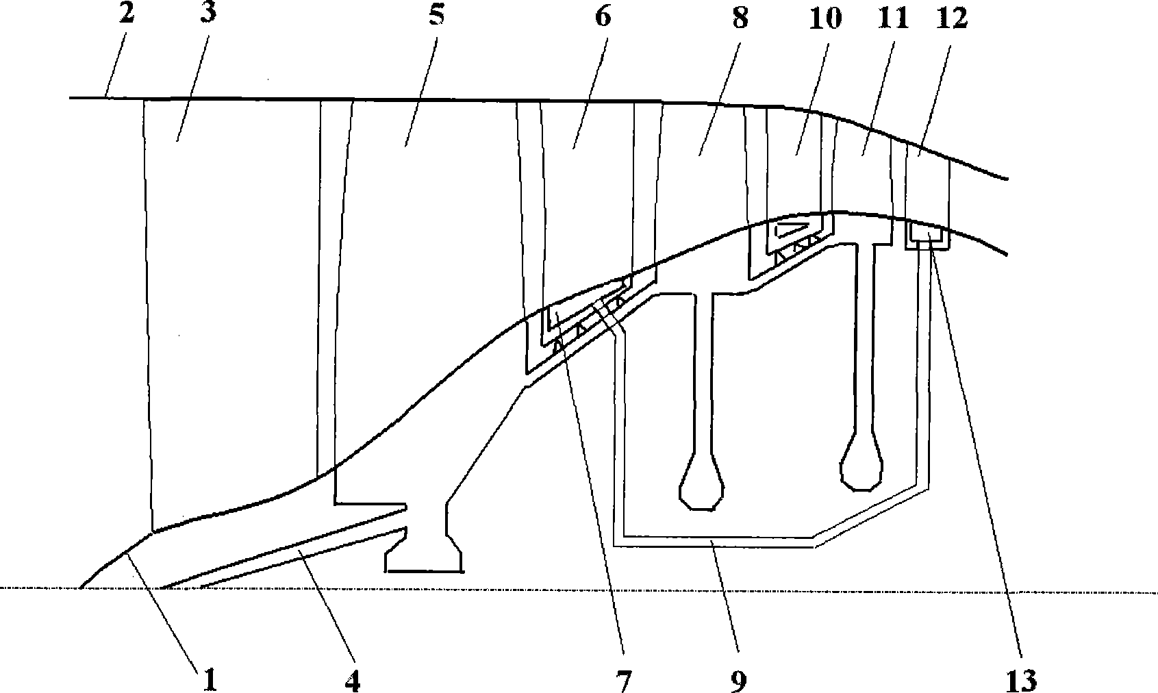
[0030] In order to describe the present invention more clearly, this specific embodiment takes a multi-blade row circulatory active flow control scheme of a turbofan engine fan component as an example, and further illustrates the present invention with reference to the accompanying drawings.

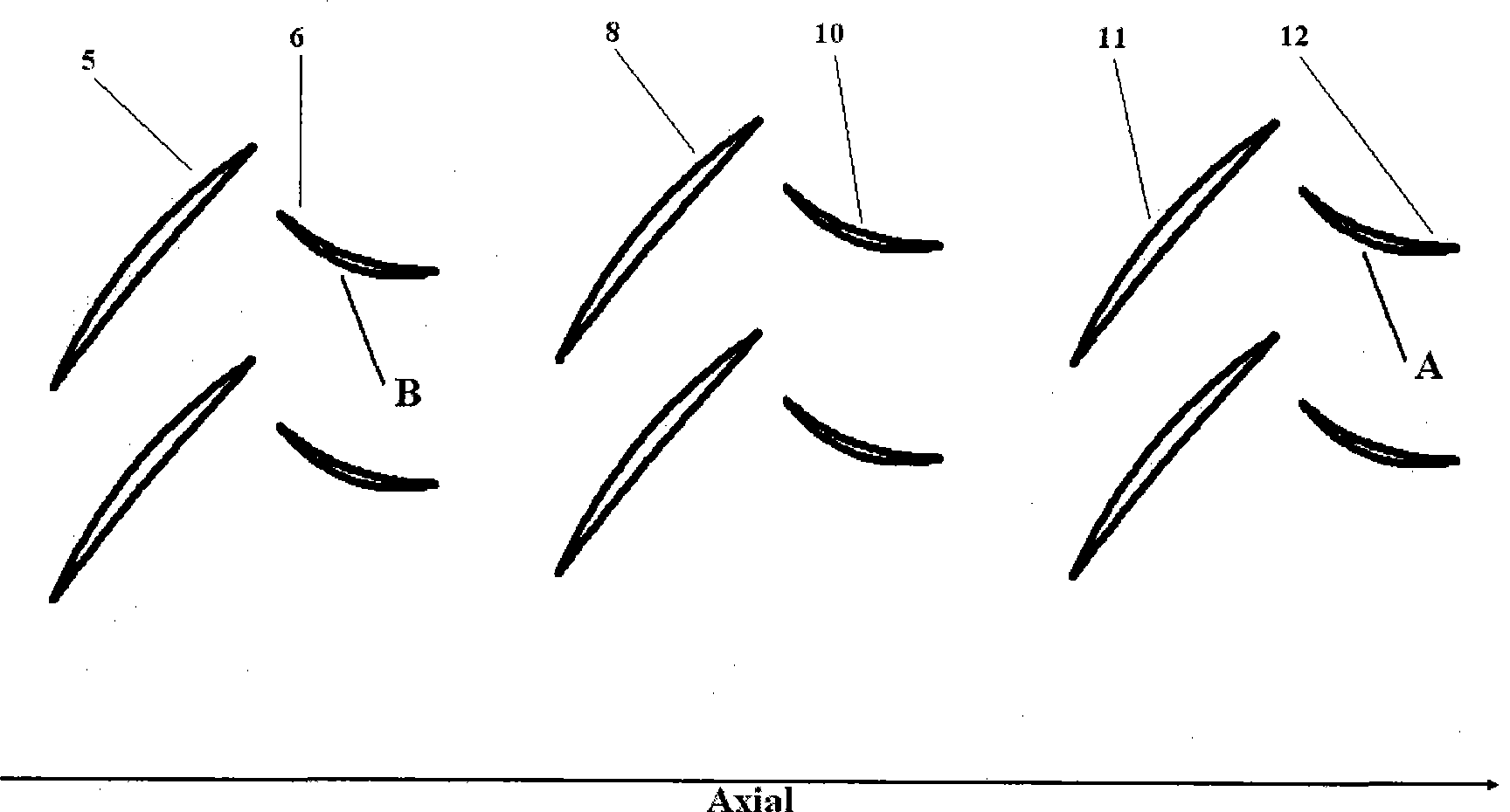
[0031] The example of the present invention is a three-stage fan with inlet guide vanes, the corresponding pressure ratios of each stage are 2.04, 1.91, and 1.60, respectively, and the load coefficients of each stage are 0.28, 0.31, and 0.29, respectively. Flow path geometries for multi-blade rows of fan components that can recirculate active flow control schemes such as figure 1 .

[0032] (1) According to the analysis of the experimental flow field of the computational fluid dynamics numerical simulation of the fan, according to the streamline of the flow field and the position of the three-dimensional separation area, the high-pressure suction blade row and the low-pressure blower bla...


PUM


Abstract

Disclosed is a method for controlling the flow of the multiple blade row circulating blowing air of compression system of aero turbofan engine. According to the calculation hydrodynamics value analog experiment flow field of a fan / compressor, static sub-blade rows which has serious separation of boundary-layer of the rear end wall are selected, the position of the separation lines of the boundary-layer on the blade row end wall in three dimensional way is determined and inspiration grooves are arranged, the air flow sucked out is collected by an annular air collection chamber on the outer surface of the end wall; the static sub-blade rows which have separation and low pressure of the boundary-layer of the front end wall are selected, the upstream position of the separation lines of the boundary-layer on the blade row end wall in three dimensional way is determined and blowing grooves are arranged, the air flow from an air source which is to be blown in is collected by an annular air collection chamber on the outer surface of the end wall; the air flow passages between high pressure and lower pressure blade row annular air collection chambers are designed; the circulating blowing air flow flows into the annular air collection chambers through the high pressure blade row air grooves, the air flow flows to the annular air collection chambers of the low pressure blade rows along the air flow passage according to the pressure gradient of the compression system, and finally the low pressure blade row blowing grooves blow the main flow to complete the circulation. The invention utilized the pressure gradient of the compression system, controls the circulating blowing air flow for the high pressure and low pressure blade rows, has simple structure, and can significantly improve the efficiency and operating margin of the compression system of the air turbofan engine.

Description

technical field [0001] The invention relates to the design and flow control of the compression system of an aviation turbofan engine (referred to as turbofan engine), and is a multi-blade cyclic active flow control method directly applied to the fan / compressor of the aviation turbofan engine. Background technique [0002] Thrust-weight ratio is an important indicator to measure the level of turbofan engine. In recent decades, with the substantial increase in the thrust-to-weight ratio of turbofan engines, the compact impeller technology that increases the fan / compressor stage pressure ratio and stage load and reduces the number of stages has become an effective way to improve the engine thrust-to-weight ratio. Under high load and large reverse pressure gradient, the proportion of the gradually thickened end wall boundary layer in the fan / compressor in the radial space of the flow channel increases, and the three-dimensional effect of the flow in the blade cascade dominates, ...

Claims


Application Information

Patent Timeline
Patent Type & Authority Applications(China)
IPC IPC(8): F04D27/00
Inventor 侯安平袁巍赵斌周盛陆亚钧
Owner BEIHANG UNIV
Why Eureka
Try Eureka