Fatigue life test stand for angular contact ball bearing

A technology of angular contact ball bearings and fatigue life, applied in the field of mechanical engineering, can solve problems such as inconvenient operation, poor coaxiality of the shaft system, high cost, etc., and achieve the effects of convenient installation and disassembly, large adjustment range, and convenient operation

Inactive Publication Date: 2009-04-29
SOUTHEAST UNIV
View PDF0 Cites 27 Cited by
  • Summary
  • Abstract
  • Description
  • Claims
  • Application Information

AI Technical Summary

Problems solved by technology

[0003] 1) The power source (drive component) is connected to the tested bearing through a coupling, and the coaxiality of the shaft system is poor. In addition, some test benches use pulley transmission. Therefore, the impact load and noise generated during the test will cause the bearing to Fatigue life test results have large errors;
[0004] 2) The horizontal structure generally adopts hydraulic loading (or other more complex mechanical loading) technology, resulting in a complex structure and high cost of the loading system;
[0005] 3) The structure of the tested bearing part is complicated, the installation and disassembly are cumbersome, and the operation is inconvenient;
[0006] 4) With the traditional mechanical transmission speed-up technology, the high-speed performance of the test bench is poor, and it is only suitable for medium and low speeds (generally less than 10000rpm)

Method used


Image

  • Fatigue life test stand for angular contact ball bearing

Examples


Embodiment 1

[0025] Angular contact ball bearing fatigue life test bench structure of the present invention is:

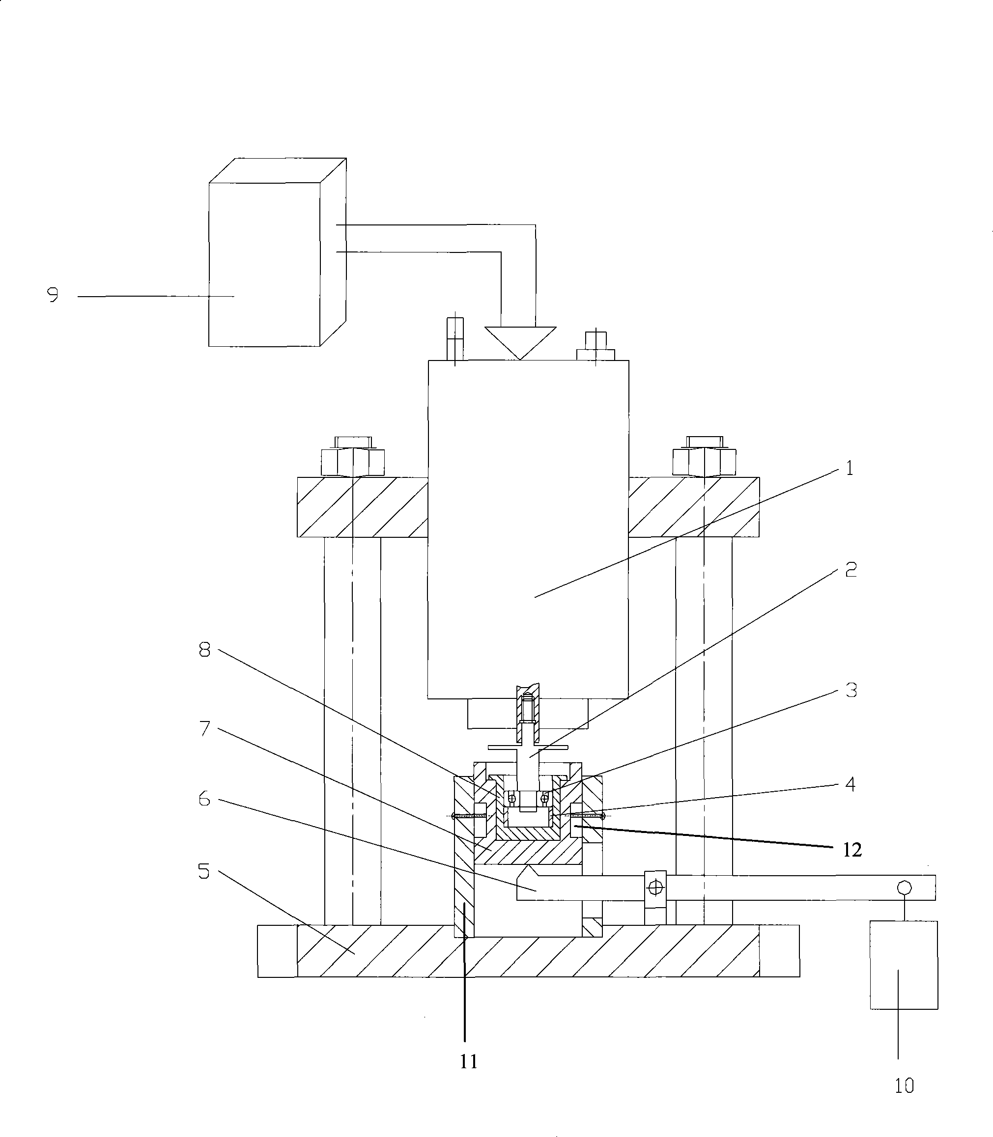
[0026] An angular contact ball bearing fatigue life test rig, the test rig includes a driving device, a tested bearing assembly, a loading device and a vertical test rig 5:

[0027] The driving device is arranged on the top of the test bench 5, and the driving device is composed of a frequency converter 9 and a high-frequency motor 1, and the transmission shaft 2 of the high-frequency motor 1 is provided with an angular contact ball bearing 3 to be tested;

[0028] The bearing assembly to be tested is coaxially arranged below the high-frequency motor 1. The assembly includes a loading sleeve 7, a bearing seat 8, a retaining ring 4 and a fixed part 11: the loading sleeve 7 is arranged on the fixed part 11 on the base of the test bench 5 Inside, a limiting device 12 is provided between the outer wall of the loading sleeve 7 and the fixed part 11, so that the loading sleeve 7 can ...


PUM


Abstract

The invention provides an apparatus for testing the fatigue life of a high-speed angular contact ball bearing. The apparatus tests the fatigue life of the angular contact ball bearing under the working condition of various rotary speeds and loads by adoption of a frequency converter to realize infinite variable speed of a high-frequency motor, adoption of a transmission shaft to drive the angular contact ball bearing to rotate at a high speed under certain pretightening force, and adoption of a weight to adjust and load the axial pretightening force. The apparatus overcomes the defects of complex structure, expensive price, trivial operation, large noise and so on of the prior apparatus for testing the fatigue life of the angular contact ball bearing, realizes zero transmission and lever loading, and has the advantages of superior high-speed performance, reliable test results, simple structure and low cost.

Description

1. Technical field [0001] The invention belongs to the technical field of mechanical engineering, and in particular relates to an angular contact ball bearing fatigue life test bench. 2. Background technology [0002] Existing technology: At present, most of the fatigue life test devices for angular contact ball bearings adopt a horizontal structure, driven by a motor, accelerated by a belt transmission, and hydraulically applied with an axial pretightening force. However, such test benches generally have the following obvious disadvantages: [0003] 1) The power source (drive component) is connected to the tested bearing through a coupling, and the coaxiality of the shaft system is poor. In addition, some test benches use pulley transmission. Therefore, the impact load and noise generated during the test will cause the bearing to Fatigue life test results have large errors; [0004] 2) The horizontal structure generally adopts hydraulic loading (or other more complex mech...

Claims


Application Information

Patent Timeline
Patent Type & Authority Applications(China)
IPC IPC(8): G01M13/04
Inventor 蒋书运
Owner SOUTHEAST UNIV
Why Eureka
Try Eureka