Driving method for liquid crystal display device

A technology of a liquid crystal display device and a driving method, which is applied to static indicators, instruments, etc., to achieve the effects of improving defects and improving display quality

Active Publication Date: 2009-04-29
NANJING CEC PANDA LCD TECH
View PDF0 Cites 10 Cited by
  • Summary
  • Abstract
  • Description
  • Claims
  • Application Information

AI Technical Summary

Problems solved by technology

And because the human eye is more sensitive to green, it is easy to obser

Method used


Image

  • Driving method for liquid crystal display device
  • Driving method for liquid crystal display device
  • Driving method for liquid crystal display device

Examples


Example Embodiment

[0023] The present invention will be further described below with reference to the drawings and typical embodiments.

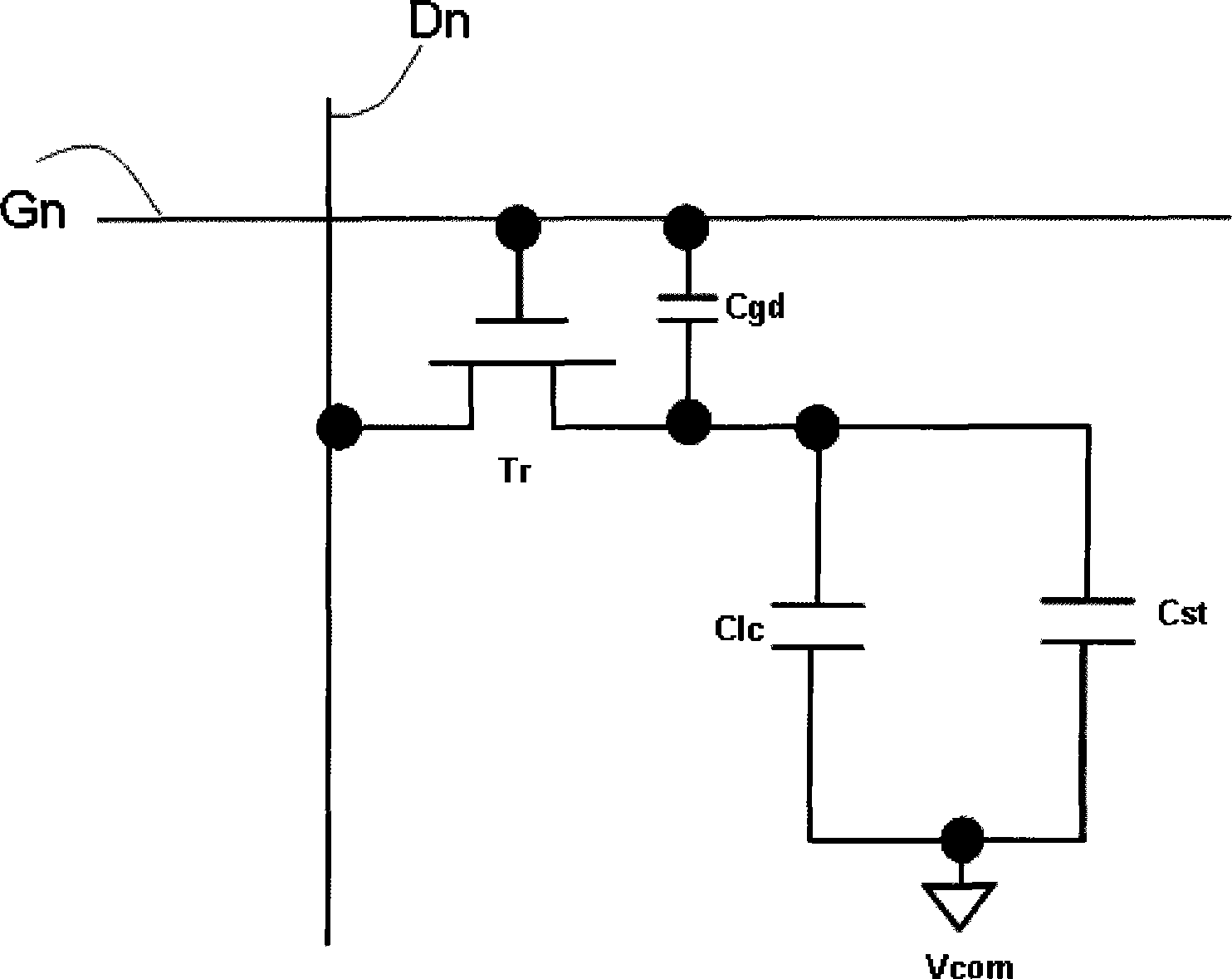
[0024] The liquid crystal display device used in the present invention includes m rows and n columns of display pixels, each pixel is controlled by a thin film transistor, each row of pixels is connected to a scan line, and each column of display pixels is connected to a data line. See Figure 4 Each pixel consists of a thin film transistor (TFT), and each row of pixels is connected to a scan line. The scan lines G1, G2...Gm are provided with scan signals by the gate driver 2. Each column of pixels is connected to a data line. The data line D1, D2...Dn is provided with data signals by the data driver 3, wherein the data lines D1, D2...Dn and the scan lines G1, G2...Gm are arranged vertically and crosswise, and the gate driver 2 and the data driver 3 are driven by the timing controller 1 respectively.

[0025] The liquid crystal display device used in the present i...


PUM


Abstract

The invention relates to a method for driving a liquid crystal display (LCD) device, and the LCD device comprises m lines and n rows of display pixels as well as one row or a plurality of rows of virtual pixels, and each of the pixels is controlled by a thin film transistor, each line of pixels are connected with a scanning beam, each row of display pixels are connected with a data link, and each row of virtual pixels are connected with a compensating data link, wherein, compensating data is generated for each line of pixels according to the whole polarity of the display data; the polarity of the compensating data is opposite to the whole polarity of the line of display data, wherein, m and n are signless integral. The method for driving the LCD device can improve the defect caused by the coupling of public voltage and enhance the display quality.

Description

technical field [0001] The invention relates to a driving method of a liquid crystal display device, in particular to a driving method of a liquid crystal display device which improves common voltage coupling. Background technique [0002] Display technology has changed significantly in recent years. Traditional CRT displays are gradually being replaced by flat panel displays, the most common of which are thin film transistor liquid crystal displays (TFT-LCDs). [0003] The equivalent circuit of a pixel of a liquid crystal display device such as figure 1 As shown: it is composed of a thin film transistor (TFT) Tr, a liquid crystal capacitor Clc, a storage capacitor Cst, a data line Dn, and a scan line Gn. One end of the liquid crystal capacitor is connected to the drain of the transistor Tr, and the other end is connected to the common voltage Vcom; Cgd is the coupling capacitance between the gate and the drain of the transistor Tr. Since there are liquid crystal capacito...

Claims


Application Information

Patent Timeline
IPC IPC(8): G09G3/36
Inventor 王志军
Owner NANJING CEC PANDA LCD TECH
Why Eureka
Try Eureka