Strip-steel flatness measuring method based on single-step phase-shift method

A measurement method and flatness technology, applied in the field of steel rolling, can solve the problems of uncertain error of strip steel fiber length, unsuitable for moving object measurement, large amount of data collection, etc., to avoid vibration and swing of strip steel, simple structure, high precision effect

Inactive Publication Date: 2011-04-20
UNIV OF SCI & TECH BEIJING
View PDF0 Cites 0 Cited by
  • Summary
  • Abstract
  • Description
  • Claims
  • Application Information

AI Technical Summary

Problems solved by technology

The traditional non-contact flatness measurement is represented by triangulation method, optical section method and Moiré method, but they have disadvantages that cannot be ignored: the principle of laser triangulation method is simple, the response speed is fast, and online data processing is easy to implement, but it has Steel vibration and swaying bring uncertain errors to the measurement of strip steel fiber length
[0004] Solving the phase is the key to obtain the three-dimensional contour of the object through the phase measurement method. At present, the commonly used methods for solving the phase include three-step phase shift, four-step phase shift, five-step phase shift and single-step phase shift, among which three-step phase shift, four-step phase shift Both phase shifting and five-step phase shifting methods require more than two images, the amount of data collection is large, and the collection time is long. It is impossible to collect enough data for those occasions with speed requirements, and it is not suitable for the measurement of moving objects.

Method used


Image

  • Strip-steel flatness measuring method based on single-step phase-shift method
  • Strip-steel flatness measuring method based on single-step phase-shift method
  • Strip-steel flatness measuring method based on single-step phase-shift method

Examples


Embodiment Construction

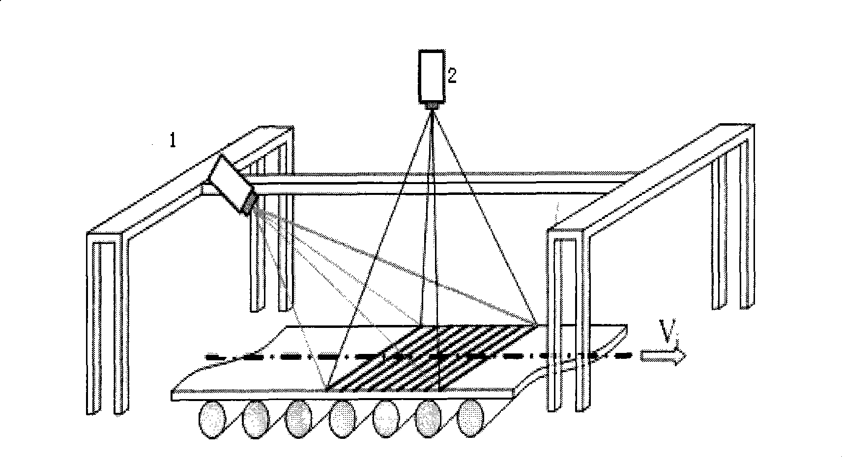
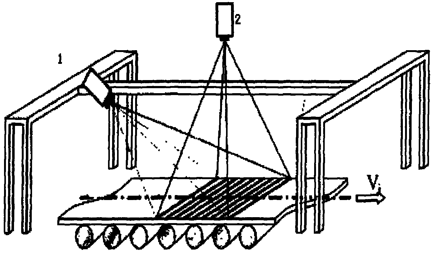
[0031] exist figure 1 In the above, the DLP (1) is installed obliquely above the center side of the steel strip, and the angle and range of projection can be properly adjusted according to the actual situation. Usually, the incident angle of the optical axis of the DLP (1) and the projected light section is more suitable in the range of 20°-50°. The installation height of the area array CCD camera (2) is the same as that of the DLP (1), and the optical axis is perpendicular to the surface of the steel strip. A filter is installed in front of the area array CCD camera (2) to filter out impurity light sources (such as hot-rolled strips) near-infrared light).

[0032] The DLP projector obliquely projects the sinusoidal grating fringe (gray value distribution according to the sinusoidal law) image compiled by the software onto the strip surface, and the deformed fringe image is taken by the area array CCD camera vertically installed directly above the center side of the strip, an...


PUM


Abstract

The invention introduces a phase measurement method to the field of flatness measurement and provides a band steel flatness measuring method based on single-step phaseshift. First, sine stripe images are programmed by a computer program, the gray value changes according to the sine discipline, and the stripe images are obliquely projected to the surface of band steel by a DLP projector. If the band steel has wave shape, the longitudinal fiber of the band steel offsets and deforms relative to a reference plane, consequently, stripes on the surface of the band steel are deformed; therefore, allprofile shape character information are contained in the deformed stripe image. A CCD camera is used for vertically shooting the deformed stripes, and height values of points on the band steel can beworked out according to the corresponding relationship between stripe image phases and band steel surface height; and finally, a flatness calculation module is used for calculating the flatness parameter. The measuring method belongs to a full-site three-dimensional measuring method and can overcome negative impacts brought to the measurement by band steel movement.

Description

technical field [0001] The invention belongs to the technical field of steel rolling, and in particular provides an on-line measurement method for the flatness of strip steel, and a specific implementation manner. Background technique [0002] In the strip rolling production process, the flatness of the strip is an important control target, which directly affects the final quality of the strip, so it is very important to install a flatness detection device at the exit of the strip mill. The traditional non-contact flatness measurement is represented by triangulation method, optical section method and Moiré method, but they have disadvantages that cannot be ignored: the principle of laser triangulation method is simple, the response speed is fast, and online data processing is easy to implement, but it has Steel vibration and swaying bring uncertain errors to the measurement of strip steel fiber length. The advantage of the optical section method is that it contains certain ...

Claims


Application Information

Patent Timeline
Patent Type & Authority Patents(China)
IPC IPC(8): G01B11/30G01B11/25B21B38/02
Inventor 徐科张会彦杨朝林周鹏
Owner UNIV OF SCI & TECH BEIJING
Why Eureka
Try Eureka