
Dryer

A drying device and drying technology, applied in the directions of drying gas arrangement, drying, and preservation of seeds by drying, etc., can solve the problems of shortening drying time, drying with unrecorded absolute humidity of exhaust air, etc., and achieve the effect of reducing moisture gradient

Inactive Publication Date: 2009-05-06
ISEKI & CO LTD
View PDF2 Cites 8 Cited by
  • Summary
  • Abstract
  • Description
  • Claims
  • Application Information

AI Technical Summary

Problems solved by technology

[0004] Although Patent Document 1 describes how to adjust the exhaust air volume to achieve the target exhaust air absolute humidity, it does not describe what kind of exhaust air absolute humidity can be targeted for drying.
[0005] In addition, in Patent Document 2 and Patent Document 3, there is no description on the technique of shortening the drying time.

Method used


Image

  • Dryer
  • Dryer
  • Dryer

Examples


Embodiment Construction

[0041] Next, the case where this Embodiment is used for a grain dryer is demonstrated.

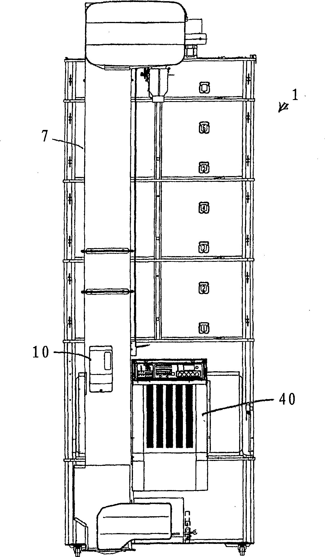
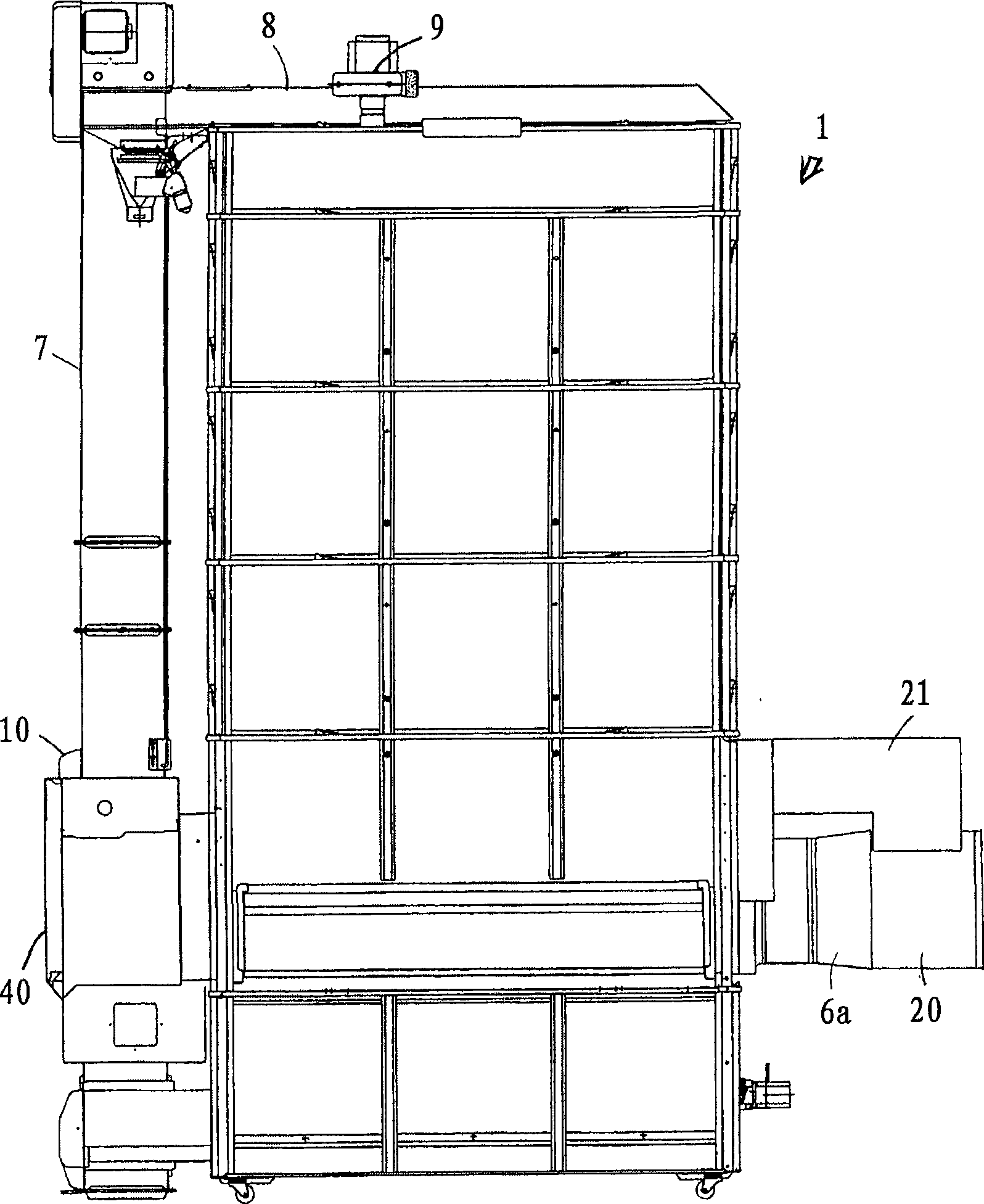
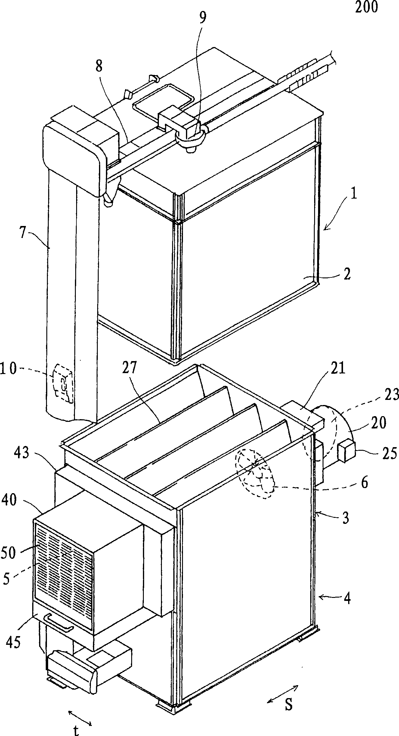
[0042]figure 1 , figure 2 It is figure showing the whole of grain dryer, image 3 It is a perspective view explaining the inside of a grain dryer. Inside the rectangular parallelepiped-shaped main body 1, there are provided in order from the top a storage section 2 for storing grains, a drying section 3 for drying the grains stored in the storage section 2 while flowing downward, and collecting and drying them in the drying section 3. The grain collection part 4 of the grain. And its structure has the structure of so-called circulation type grain dryer as follows: the grain that enters the storage part 2 is supplied to the grain collecting part 5 after being dried in the drying part 3, and is supplied to the storage part 2 again and conditioned. quality treatment.

[0043] In addition, in this embodiment, the longitudinal direction s of the main body 1 is called a front-back direction...


PUM


Abstract

The present invention provides a drying device which can dry continuously and stably with a high speed and can prevent the granular object rupture of corn. The drying device is provided with a control part (F1) which outputs a signal for reducing the returning amount of air exhausting to regulating devices (22, 23) when a state that the absolute humidity (HD) of drying air obtains the absolute humidity (HF) of saturated steam pressure or higher than the upper limit absolute humidity (beta*HF) that is set near the absolute humidity (HF) is detected; and outputs a signal for increasing the returning amount of air exhausting to the regulating devices (22, 23) when a state that the absolute humidity (HD) of drying air is lower than the lower limit absolute humidity (alpha*HF) lower than the absolute humidity (HF) of saturated steam pressure for a preset value is detected.

Description

technical field [0001] The present invention relates to a drying device for agricultural products such as grains and shiitake mushrooms, marine products, or wood. Background technique [0002] Patent Document 1 (Japanese Unexamined Patent Application Publication No. 2007-10247) describes a drying device that returns exhaust air and merges with warm air to dry. [0003] In addition, in Patent Document 2 (Japanese Unexamined Patent Publication No. 61-195266) and Patent Document 3 (Japanese Patent No. 2599270), it is described that when the mixing ratio of the exhausted warm air at the initial stage of drying is a high value, it decreases further. The amount of exhausted hot air used increases the amount of exhausted warm air used in stages as the drying progresses to the middle of the drying period and the completion period. [0004] Although Patent Document 1 describes that the exhaust air volume is adjusted to achieve the target exhaust air absolute humidity, it does not de...

Claims


Application Information

Patent Timeline
IPC IPC(8): F26B21/04F26B21/10
CPCA23B4/031A23B9/08F26B17/1425
Inventor 西野荣治向山直树
Owner ISEKI & CO LTD
Learn More