DC bus bar connection construction for large power three-phase inverter

A three-phase inverter, DC bus technology, applied in output power conversion devices, bus/line layout, electrical components, etc., to increase distributed capacitance, reduce line impedance, and achieve the effect of overlapping ranges

Inactive Publication Date: 2009-05-06
LIEBERT
View PDF0 Cites 9 Cited by
  • Summary
  • Abstract
  • Description
  • Claims
  • Application Information

AI Technical Summary

Problems solved by technology

[0004] The technical problem to be solved by the present invention is to provide a combination of capacitor group installation and reduction of ripple current between capacitors in the bus connection of high-power three-phase inverters in the prior art. Group installation and DC bus connection structure of high-power three-phase inverters that can reduce the ripple circuit between capacitors

Method used


Image

  • DC bus bar connection construction for large power three-phase inverter
  • DC bus bar connection construction for large power three-phase inverter
  • DC bus bar connection construction for large power three-phase inverter

Examples


Embodiment Construction

[0031] Figure 5 to Figure 9 A preferred embodiment of the invention is shown.

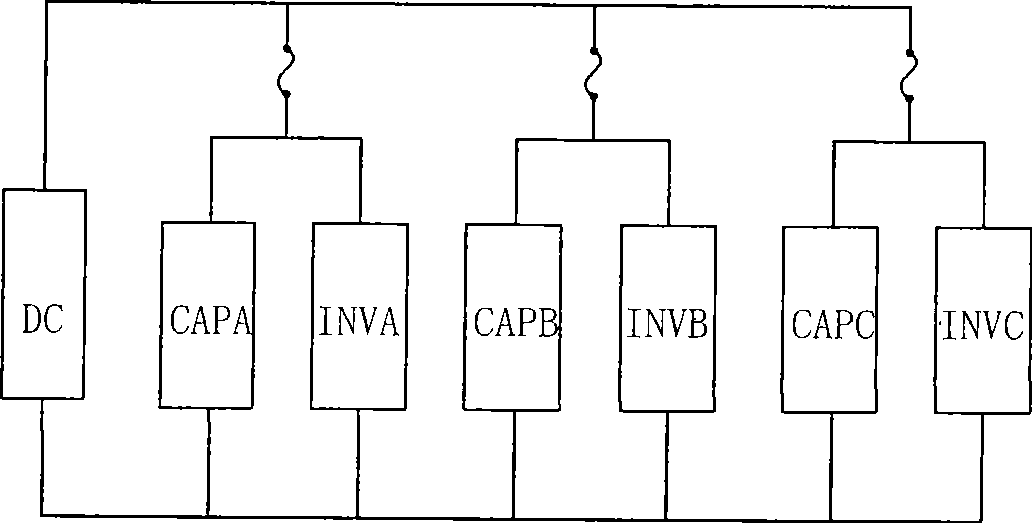
[0032] see Figure 5 As shown, in this embodiment, the bus connection of the high-power three-phase inverter includes three capacitor modules (CAPA, CAPB, CAPC) 2, 4, 6 and three inverter switching tube modules (INVA, INVB, INVC ) 3, 5, 7, each capacitor module is connected in parallel with an inverter switching tube module nearby, and the capacitor module and the inverter switching tube module are connected in parallel to a direct current power supply (DC) 1 . A fuse 8 is provided between the capacitor module, the inverter switch tube module and the DC power supply (DC) 1 after parallel connection.

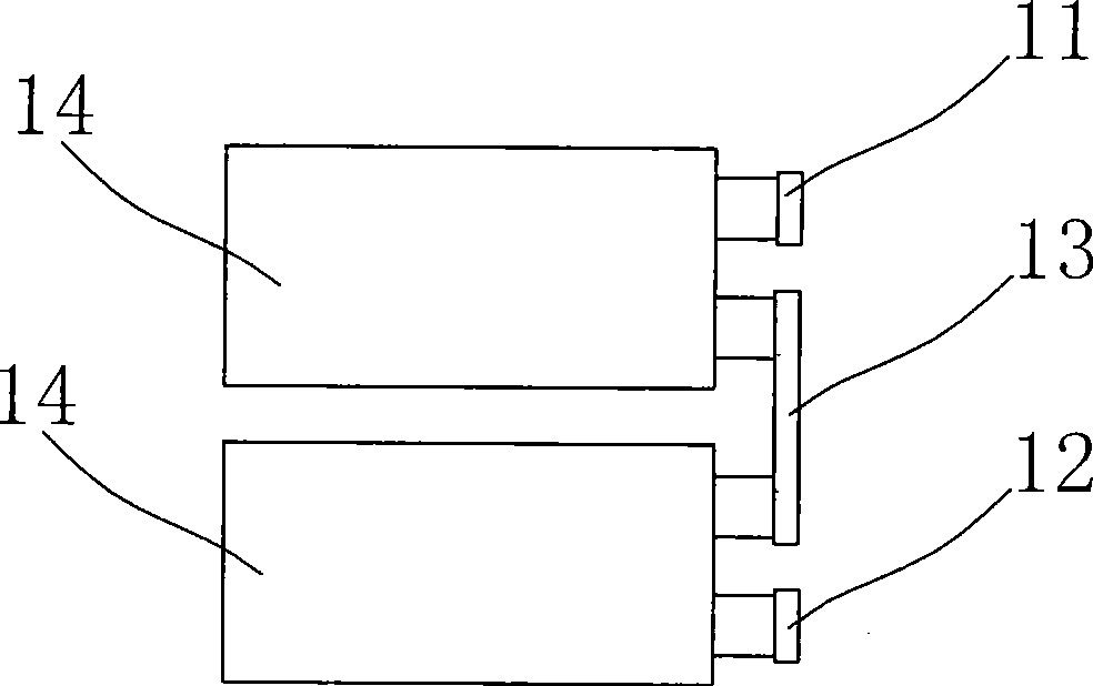
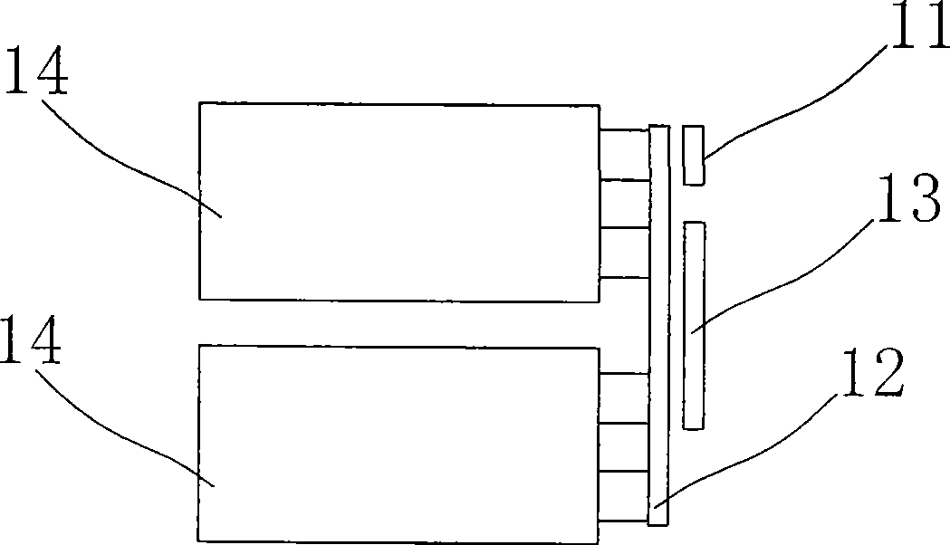
[0033] refer to Image 6 , Figure 7 As shown, in this embodiment, the capacitor module 4 is composed of eight electrolytic capacitors 41 connected by copper bars. The connected copper bars include a positive electrode copper bar 42, a negative electrode copper bar 43, and an intermediate connect...


PUM


Abstract

The invention relates to a direct-current bus connection structure of a three-phase high-power inverter. In order to solve the problems that the grouping installation of capacitors is not considered in the prior three-phase high-power inverter and the ripple current between the capacitors is reduced, the invention provides a direct-current bus connection structure of the three-phase high-power inverter, which comprises a direct-current power supply, at least two capacitor modules and an inverted switching tube module, wherein the capacitor modules are connected with the inverted switching tube module in parallel, lapped copper bars with vertical laminated structures are arranged between the two adjacent capacitor modules and connected in parallel, and the capacitor modules are connected with the direct-current power supply after being connected with the inverted switching tube module in parallel. By adopting the connection, all the capacitor modules can bear the energy requirement of the entire output power together, and the utilization ratio of the capacitance is improved; the vertical laminated structures of the anode and the cathode copper bars of the capacitor modules, the line impedance and the stray inductance parameter are minimized so as to reduce the ripple current between the capacitor modules; and the capacitor modules adopt the independent structural design, thereby facilitating distributed installation and maintenance.

Description

technical field [0001] The invention relates to an inverter, and more specifically, relates to a DC bus bar connection structure of a high-power three-phase inverter. Background technique [0002] In high-power three-phase inverter products, the layout design of its components has higher requirements in terms of maintainability, and the unit components often adopt a modular design. In the traditional high-power three-phase inverter, the number of electrolytic capacitors is large, the volume and weight are large, and the overall installation is difficult. Therefore, in this type of high-power inverter, the capacitors are installed in groups. Such as figure 1 As shown, in the traditional high-power three-phase inverter, the capacitor adopts a modular design. In this inverter, three capacitor modules (CAPA, CAPB, CAPC) and three inverter switch tube modules (INVA , INVB, INVC), each capacitor module is connected in parallel with an inverter switching tube module, and then con...

Claims


Application Information

Patent Timeline
Patent Type & Authority Applications(China)
IPC IPC(8): H02M1/00H02B1/20
Inventor 顾锦筛
Owner LIEBERT
Why Eureka
Try Eureka