Unlock instant, AI-driven research and patent intelligence for your innovation.

Axle count sensor

A technology of axle counting sensors and sensing devices, which is applied in the direction of instruments, counting mechanisms/items, vehicle route interaction equipment, etc., can solve the problems of complex structure, temperature resistance and durability limitations, and achieve good effect and simple structure

Inactive Publication Date: 2009-05-13
方阵(北京)科技有限公司
View PDF0 Cites 7 Cited by
  • Summary
  • Abstract
  • Description
  • Claims
  • Application Information

AI Technical Summary

Problems solved by technology

[0004] At present, the track sensor with the above-mentioned structure has a complex structure due to the use of electrical components, and its temperature resistance and durability are limited for outdoor equipment.

Method used


Image

  • Axle count sensor
  • Axle count sensor
  • Axle count sensor

Examples


Embodiment Construction

[0017] The following examples are used to illustrate the present invention, but are not intended to limit the scope of the present invention.

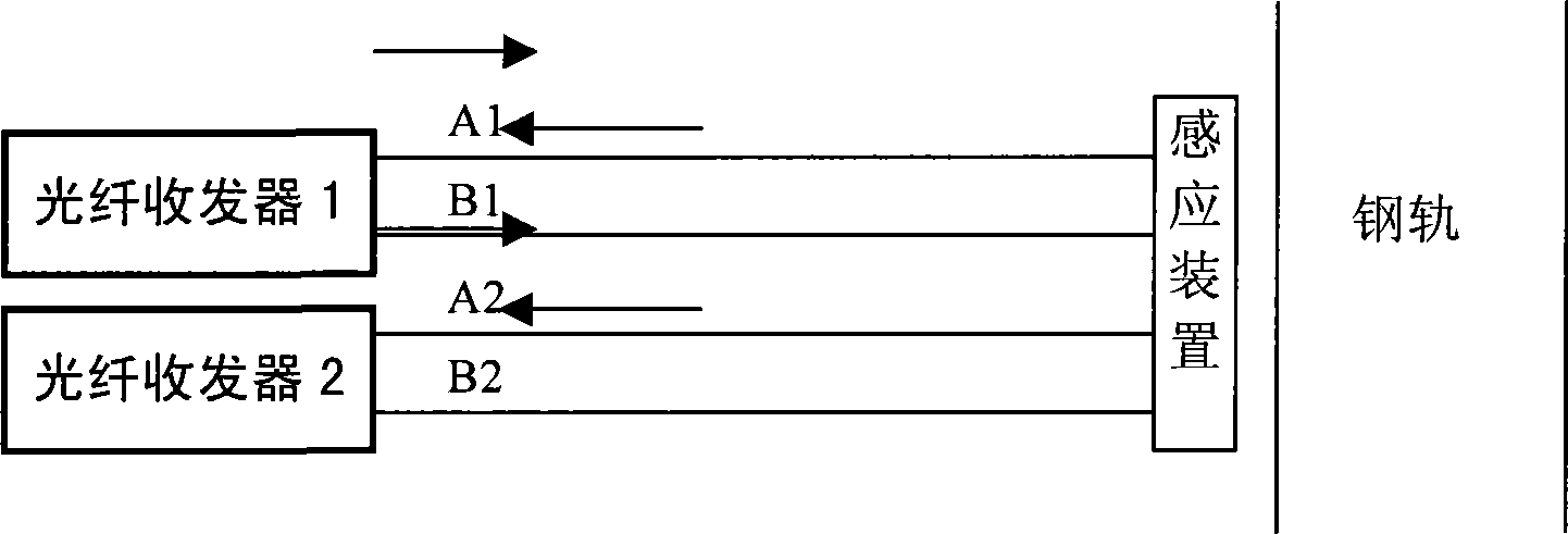
[0018] The axle counting sensor of the present invention comprises indoor optical fiber transceiver, optical fiber and outdoor sensing device, such as figure 1 As shown, the optical fiber transceiver 1 transmits optical signals to the sensing device through the optical fiber A1, and the sensing device is installed on both sides of the track (slightly higher than the guide rail) or at the bottom of the track. When no locomotive passes, the sensing device allows the light signal to pass through, and the optical fiber transceiver 1 can receive the sent light signal through the optical fiber B1. Transmission, the optical fiber transceiver 1 cannot receive the optical signal, so the passing and interruption of the axle is converted into a changing optical signal, so the optical fiber transceiver 1 converts the changing optical signal into a...


PUM


Abstract

The invention relates to an axle counting sensor which comprises a fiber optic transceiver, optical fiber and a sensing device, wherein, the fiber optic transceiver sends optical signals to the sensing device through the optical fiber, the make-break for the optical signals is performed by the sensing device, and the fiber optic transceiver receives the optical signals passing through the sensing device. The axle counting sensor has the advantages of high and low temperature resistance and simple structure.

Description

technical field [0001] The invention relates to a track axle counting sensor, in particular to an axle counting sensor using an optical fiber transceiver. Background technique [0002] The axle counter is used to detect the number of axles of the train passing a certain point (axle counting point) on the railway, to check the space between two axle counting points or in the track section, or to determine the time when the train passes the axle counting point, and to automatically correct the train Equipment for mileage etc. [0003] Among them, the axle counter sensor is the basic equipment of the axle counter, and its function is to convert the number of axles passed by locomotives and vehicles into electrical pulse signals. At present, the electromagnetic type is generally used. The electromagnetic sensor consists of three parts: a magnetic head, a transmitter, and a receiver. The magnetic head has a sending coil and a receiving coil respectively mounted on both sides o...

Claims


Application Information

Patent Timeline
IPC IPC(8): B61L1/16G06M1/272
Inventor 舒莉莉田红波赵华雄
Owner 方阵(北京)科技有限公司
Features
  • R&D
  • Intellectual Property
  • Life Sciences
  • Materials
  • Tech Scout
  • Unparalleled Data Quality
  • Higher Quality Content
  • 60% Fewer Hallucinations
Learn More