Method to determine the fuel temperature in a common rail injection system

A technology of injection system, fuel temperature, applied in the application of thermometer, temperature measurement in motor, thermometer, etc., to achieve the effect of accurate and stable electronic regulation, reduce cost and error rate

Inactive Publication Date: 2009-05-13
CONTINENTAL AUTOMOTIVE GMBH
View PDF2 Cites 9 Cited by
  • Summary
  • Abstract
  • Description
  • Claims
  • Application Information

AI Technical Summary

Problems solved by technology

Also, this method only allows to determine the fuel temperature at the injector

Method used


Image

  • Method to determine the fuel temperature in a common rail injection system
  • Method to determine the fuel temperature in a common rail injection system
  • Method to determine the fuel temperature in a common rail injection system

Examples


Embodiment Construction

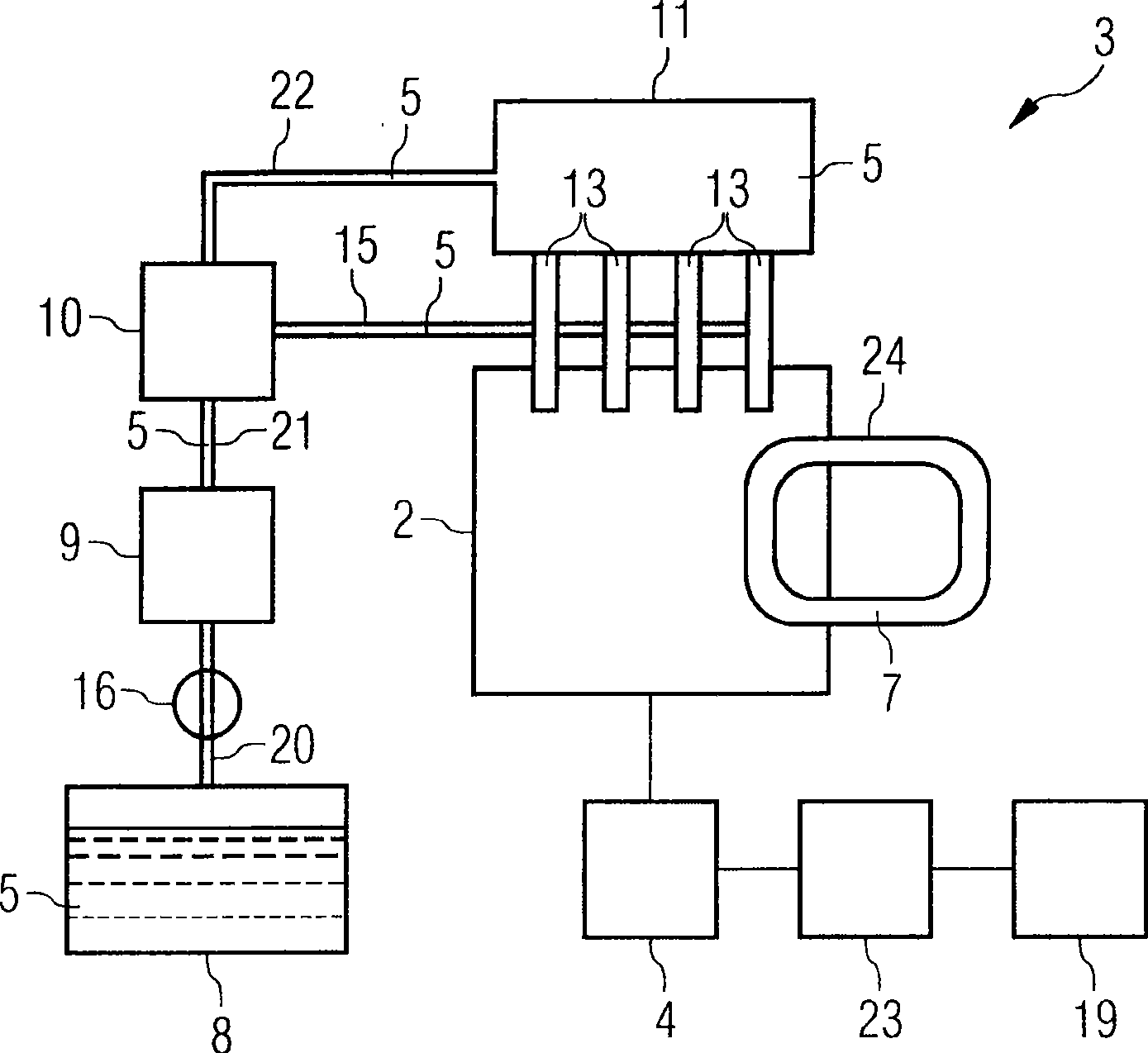
[0022] figure 1 A schematic diagram of a common rail injection system 3 that can be used with the engine 2 is shown. Fuel 5 flows from fuel tank 8 via first fuel line 20 to backing pump 9 of high-pressure pump 10 . The backing pump 9 pumps fuel 5 to the high-pressure pump 10 via the second fuel line 21 . The high-pressure pump 10 pumps the fuel 5 to the common rail 11 at high pressure FPSP via the third fuel line 22 . Fuel 5 is injected into engine 2 from common rail 11 through several injectors 13 . Fuel leakage at the injector 13 is conveyed back to the high-pressure pump 10 via a leakage line 15 .

[0023] The engine 2 is connected to a cooling water circuit 24 . The cooling water 7 circulating in the cooling water circuit 24 is used to cool the engine 2 . The temperature TCO of the cooling water 7 can be used to measure the temperature of the engine 2 .

[0024] The engine 2 is connected to an engine control unit 4 . The engine control unit 4 is connected to a tempe...


PUM


Abstract

In a method to determine the temperature of a fuel in a common rail injection system of an engine, the fuel temperature at one place of the common rail injection system is calculated from a fuel temperature at another place of the common rail injection system.

Description

technical field [0001] The invention relates to a method and a control unit for determining the temperature of fuel in a direct injection system, in particular a method and a control unit for determining the temperature of fuel in a common rail injection system of a vehicle, wherein the fuel is pumped from the fuel tank to the common rail at high pressure by a high pressure pump And then flow to the injector connected to the common rail. Background technique [0002] Engine Operation It is known to utilize an engine control unit to control ignition, fuel injection and other functions of the engine. Typical input signals to such a controller are engine revolutions per minute, pedal (eg, gas pedal) position, and temperature and pressure of fuel. In order to precisely regulate fuel injection in a common rail injection system, it is desirable to know the fuel temperature at several locations of the common rail injection system, especially within the common rail and at the injec...

Claims


Application Information

Patent Timeline
Patent Type & Authority Applications(China)
IPC IPC(8): F02D41/00F02D41/38F02D41/40
CPCF02D2200/0606F02M65/00G01K7/42F02M63/0225F02D41/3809G01K2205/00
Inventor G·巴拉M·博尼特H·李J·张
Owner CONTINENTAL AUTOMOTIVE GMBH
Why Eureka
Try Eureka