Supercharge Your Innovation With Domain-Expert AI Agents!

Compensation type pressure regulating valve used for force value stabilization

A pressure regulation and compensation technology, applied in fluid pressure actuators, balance valves, valve devices, etc., can solve the problems of high cost of hydraulic servo systems, complex control software modeling, and heavy software programming workload, etc., to achieve Good social benefits, realize stepless adjustment and compensation of leakage, and avoid personal injury

Inactive Publication Date: 2009-05-13
SHAANXI ELECTRICAL APPLIANCE RES INST
View PDF0 Cites 0 Cited by
  • Summary
  • Abstract
  • Description
  • Claims
  • Application Information

AI Technical Summary

Problems solved by technology

1. There is a leakage problem in the hydraulic system
2. The characteristics of the hydraulic system determine that the actuator must have hydraulic hysteresis, slow creep and vibration problems at low speeds
2. Leakage of each sealing joint
[0005] In order to maintain the stability of the loading force value in the high-demand force loading system, a closed-loop control of the hydraulic servo system controlled by a microcomputer is often used to compensate the leakage amount. The characteristic is that the leakage amount can be compensated and the force value can be stabilized. The system also has problems such as hydraulic hysteresis, slow creep and vibration, which lead to control accuracy, complex modeling of control software, heavy software programming workload, and high cost of hydraulic servo system

Method used


Image

  • Compensation type pressure regulating valve used for force value stabilization

Examples


Embodiment Construction

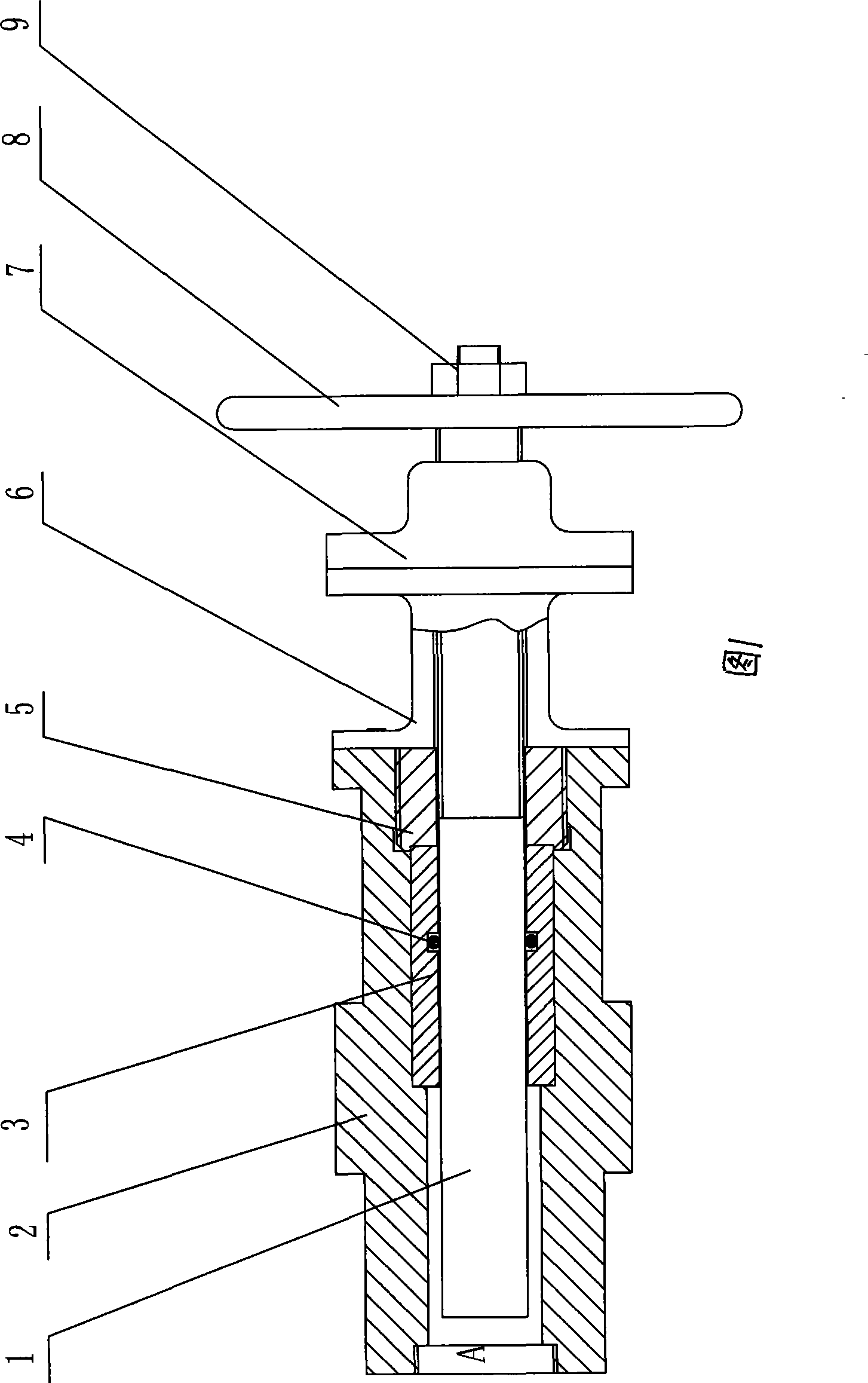
[0039] As shown in Figure 1, the valve body 2 is the carrier and body of the compensating pressure regulating valve, a sealing sliding sleeve 3 is provided between the valve body 2 and the valve core 1, and a There is a high-pressure sealing ring 4, and the sealing sliding sleeve 3 and the valve body 2 are tightly fixed through the retaining ring 5; the other part of the valve core 1 is provided with an extension sleeve 6, a protective sleeve 7 and a manual adjustment wheel 8, and the extension sleeve 6 is connected with the valve body. The body 2 is connected, the protective cover 7 is located between the extension sleeve 6 and the manual adjustment wheel 8, and the manual adjustment wheel 8 is fixed on the spool 1 with a nut 9.

[0040] When in use, the compensating pressure regulating valve is connected in parallel with the hydraulic circuit through the A port. By turning the manual adjustment wheel, the valve core moves to the left, thereby reducing the volume of the cavity...


PUM


Abstract

The invention provides a compensating pressure regulating valve used for steadying pressure value, comprising a valve body and a valve plug; the compensating pressure regulating valve is characterized in that the valve plug is connected with the valve body by an obturating ring and a sealing slide bushing which is arranged between the valve body and the valve plug, a high pressure sealing ring is arranged between valve plug and the sealing slide bushing, and the sealing slide bushing and the valve body are closely fixed by a retainer ring; the other part of the valve plug is provided with an elongated sleeve, a protective casing and a manual regulation wheel, wherein, the elongated sleeve is connected with the valve body, the protective casing is arranged between the elongated sleeve and the manual regulation wheel, and the manual regulation wheel is fixed on the valve plug by a nut. The compensating pressure regulating valve provided by the invention can effectively maintain the pressure loss of a hydraulic system and keep the pressure value comparatively stable when in the loading process of the pressure value; on the premise that automation is not requested, the compensating pressure regulating valve can completely replace a hydraulic servo system.

Description

technical field [0001] The invention relates to a special pressure regulating valve in a force loading system. Background technique [0002] For force loading, the hydraulic system has the advantages of high loading efficiency, large loading force, high efficiency, small footprint, easy overload protection, safety and reliability, and stable movement. However, the leakage (including internal leakage and external leakage) of the hydraulic system restricts the application of the hydraulic system in the high-demand force loading system. [0003] There are two main reasons for the inability to maintain a stable force value in a high-demand force value loading system. 1. There is a leakage problem in the hydraulic system. 2. The characteristics of the hydraulic system determine that the actuator must have hydraulic hysteresis, slow creep and vibration problems at low speeds. [0004] The main reasons for hydraulic system leakage: 1. Internal leakage of various control valves, ...

Claims


Application Information

Patent Timeline
Patent Type & Authority Applications(China)
IPC IPC(8): F16K17/36F16K31/60F15B13/00
Inventor 张荣军刘统春
Owner SHAANXI ELECTRICAL APPLIANCE RES INST
Features
  • R&D
  • Intellectual Property
  • Life Sciences
  • Materials
  • Tech Scout
  • Unparalleled Data Quality
  • Higher Quality Content
  • 60% Fewer Hallucinations
Learn More