
Gas sensor

A gas sensor and gas composition technology, which can be used in instruments, scientific instruments, measuring devices, etc., can solve problems such as difficulties, and achieve the effects of improving assembly performance, high reliability, and preventing warpage.

Active Publication Date: 2009-05-13
NGK SPARK PLUG CO LTD
View PDF3 Cites 8 Cited by
  • Summary
  • Abstract
  • Description
  • Claims
  • Application Information

AI Technical Summary

Problems solved by technology

However, there are limitations in changing the material considering the performance, strength and durability of the gas sensing element
To date, it has been difficult to sufficiently reduce the variance in sintering shrinkage to prevent warpage while maintaining good sensor performance and physical properties

Method used


Image

  • Gas sensor
  • Gas sensor
  • Gas sensor

Examples


Embodiment 1

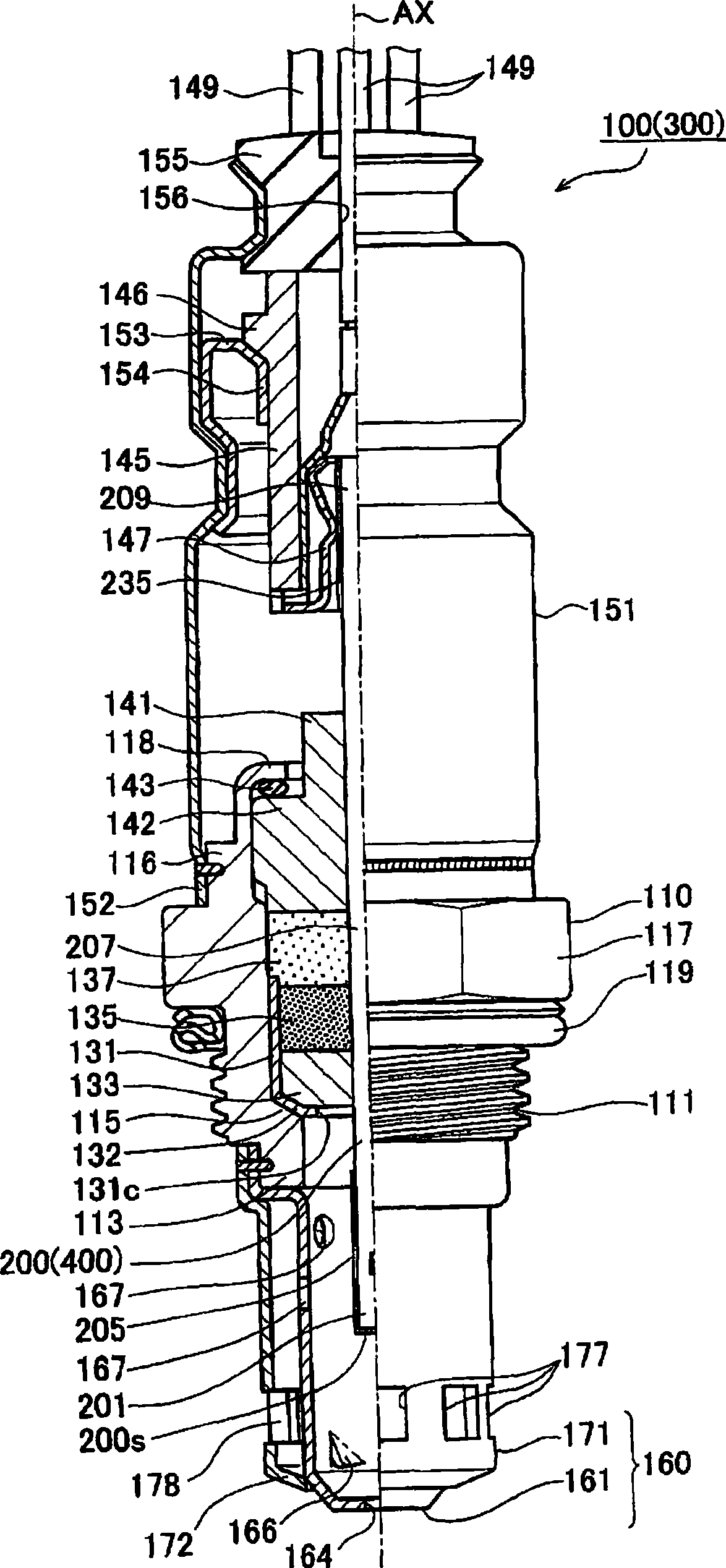
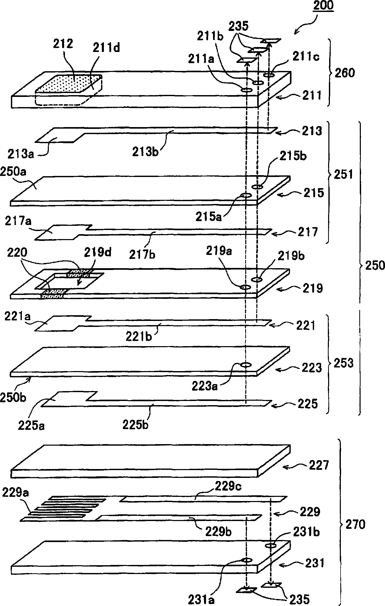
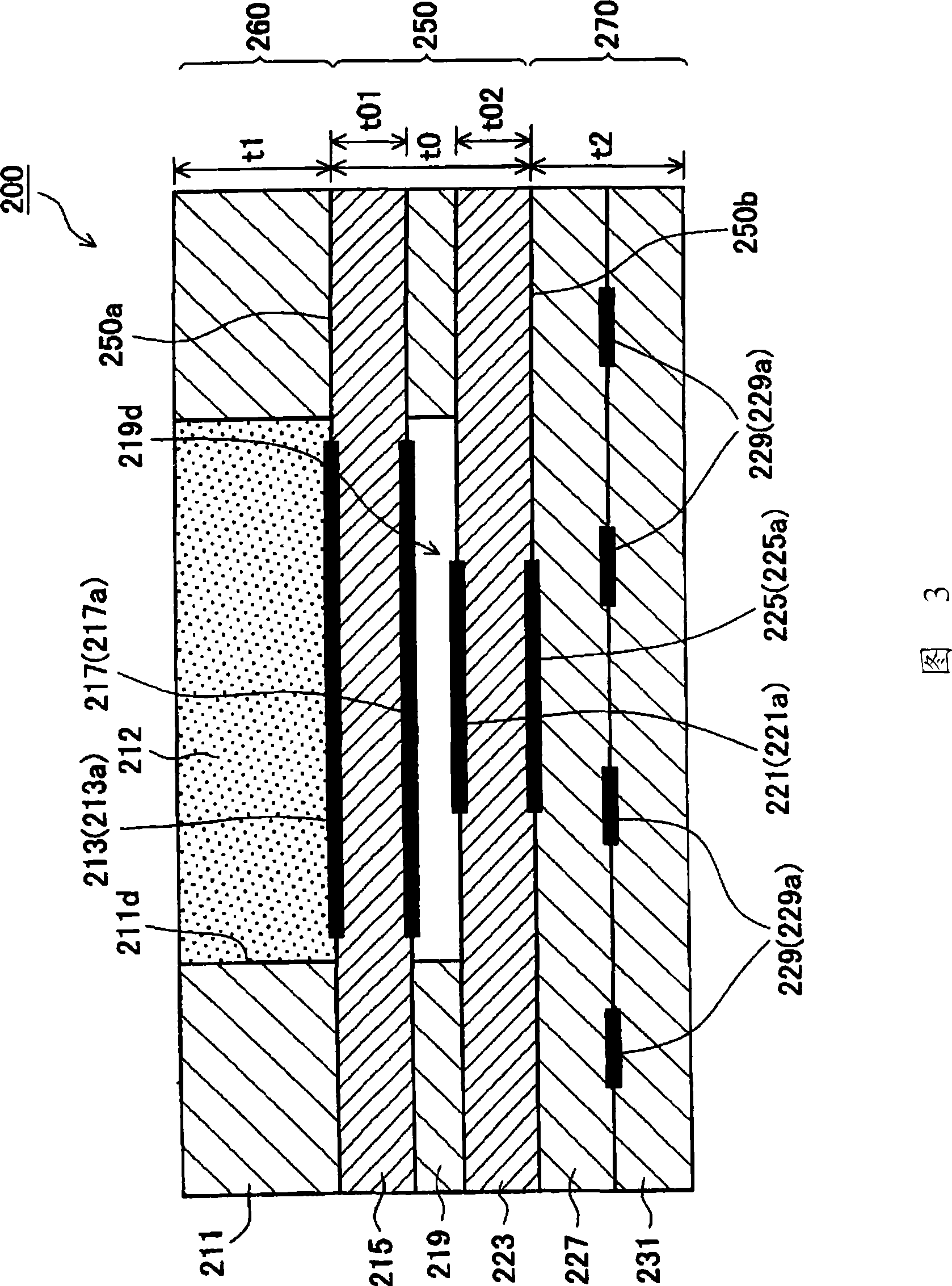
[0035] Embodiments of the present invention will be described below with reference to the drawings. figure 1 The gas sensor 100 according to Embodiment 1 is shown. also, figure 2 It is an exploded perspective view showing the detection element 200 of the gas sensor 100 . In addition, FIGS. 3 and 4 are cross-sectional views respectively showing a front end side portion and a base end side portion of the detection element 200 . In addition, in figure 1 In the drawing, the lower side in the figure is the distal side in the direction of the axis AX (hereinafter also referred to as "the distal side"), and the upper side in the figure is the proximal side in the direction of the axis AX (hereinafter referred to as the "proximal side"). In addition, in figure 2 In the figure, the left side in the figure is the front end side, and the right side in the figure is the base end side.

[0036] The present embodiment shows, as an example of the gas sensor 100 , a wide band air-fuel ...

Embodiment 2

[0091] Next, Example 2 will be described. Figure 5 is an exploded perspective view of the detection element 400 constituting the gas sensor 300 according to the above aspect of the present invention. In addition, FIGS. 6 and 7 are cross-sectional views respectively showing a front end side portion and a base end side of the detection element 400 . In the gas sensor 300 according to the present embodiment, the pattern of the detection element 400 is different from the pattern of the detection element 200 of the gas sensor 100 according to the embodiment 1. Other features are basically similar to those in Embodiment 1 above. Descriptions of parts similar to those of Embodiment 1 are omitted or simplified.

[0092] The detection element 400 according to Embodiment 2 is formed by simultaneously sintering mutually stacked layers containing different main components, and has a plate shape (ie, a plate strip) extending in the axis AX direction. The detection element 400 includes ...

Embodiment 3

[0118] Next, Example 3 will be described. Figure 8 is an exploded perspective view showing the detection element 600 of the gas sensor 500 according to the third embodiment. In addition, FIG. 9 is a cross-sectional view showing a front end side portion of the detection element 600 . In the gas sensor according to Embodiment 3, the pattern of the detection element 600 is different from the pattern of the detection element 200 of the gas sensor 100 according to Embodiment 1. Other features are basically similar to those in Embodiment 1 above, and descriptions of parts similar to those in Embodiment 1 are omitted or simplified.

[0119] The detecting element 600 according to Embodiment 3 is formed by simultaneously sintering mutually stacked layers containing different main components, and has a plate shape (ie, a plate strip) extending in the axis AX direction. The detection element 600 includes a sensing unit 650 , a porous layer 612 , a shielding layer 610 , an introduction...


PUM

PropertyMeasurementUnit
porosityaaaaaaaaaa

Abstract

A gas sensor including a detection element having a stacked structure configured to detect a specified gas component contained in a gas to be detected. The detection element includes: a sensing portion including one or more solid electrolyte layers containing a first material as a main component and having a first surface and a second surface opposite the first surface; a first portion stacked onthe first surface and including one or more first base layers containing a second material as a main component different from the first material; and a second portion stacked on the second surface and including one or more second base layers containing the second material. A total thickness of the one or more second base layers in a stacking direction is not less than 80% but not more than 120% of a total thickness of the one or more first base layers.

Description

technical field [0001] The present invention relates to a gas sensor including a detection element configured to detect a specific gas component contained in a gas to be measured. An example of the gas sensor is a gas sensor having a laminated detection element made by simultaneously sintering a plurality of laminated layers containing different main components. Background technique [0002] There is known a gas sensor that is mounted to an exhaust pipe of an automobile and includes a detection element configured to change an electromotive force or a resistance value according to the concentration of a specific component of exhaust gas (for example, nitrogen oxide, oxygen, etc.). Stacked detection elements are also known which are produced by simultaneous sintering of a plurality of stacked layers having different main compositions. If the detection element is formed by simultaneous sintering, the sintering process is completed at the same time, and lamination process is no...

Claims


Application Information

Patent Timeline
Patent Type & Authority Applications(China)
IPC IPC(8): G01N27/407
CPCG01N27/4071
Inventor 古田畅雄森茂树
Owner NGK SPARK PLUG CO LTD
Learn More