Environment-friendly energy-saving electric arc furnace control device

A control device and electric arc furnace technology, applied in electric controllers, electrical program control, program control in sequence/logic controllers, etc., can solve problems such as large influence on the power grid, low production efficiency, and large unit consumption, and achieve tripping The effect of reducing the number of times, improving production efficiency, and reducing consumption

Inactive Publication Date: 2009-05-13
HARBIN PATEERN SCI & TECH
View PDF0 Cites 1 Cited by
  • Summary
  • Abstract
  • Description
  • Claims
  • Application Information

AI Technical Summary

Problems solved by technology

One of the most important problems is that it has a great impact on the power grid, and the other is that the production efficiency is low and the unit consumption is large

Method used


Image

  • Environment-friendly energy-saving electric arc furnace control device
  • Environment-friendly energy-saving electric arc furnace control device
  • Environment-friendly energy-saving electric arc furnace control device

Examples


Embodiment 1

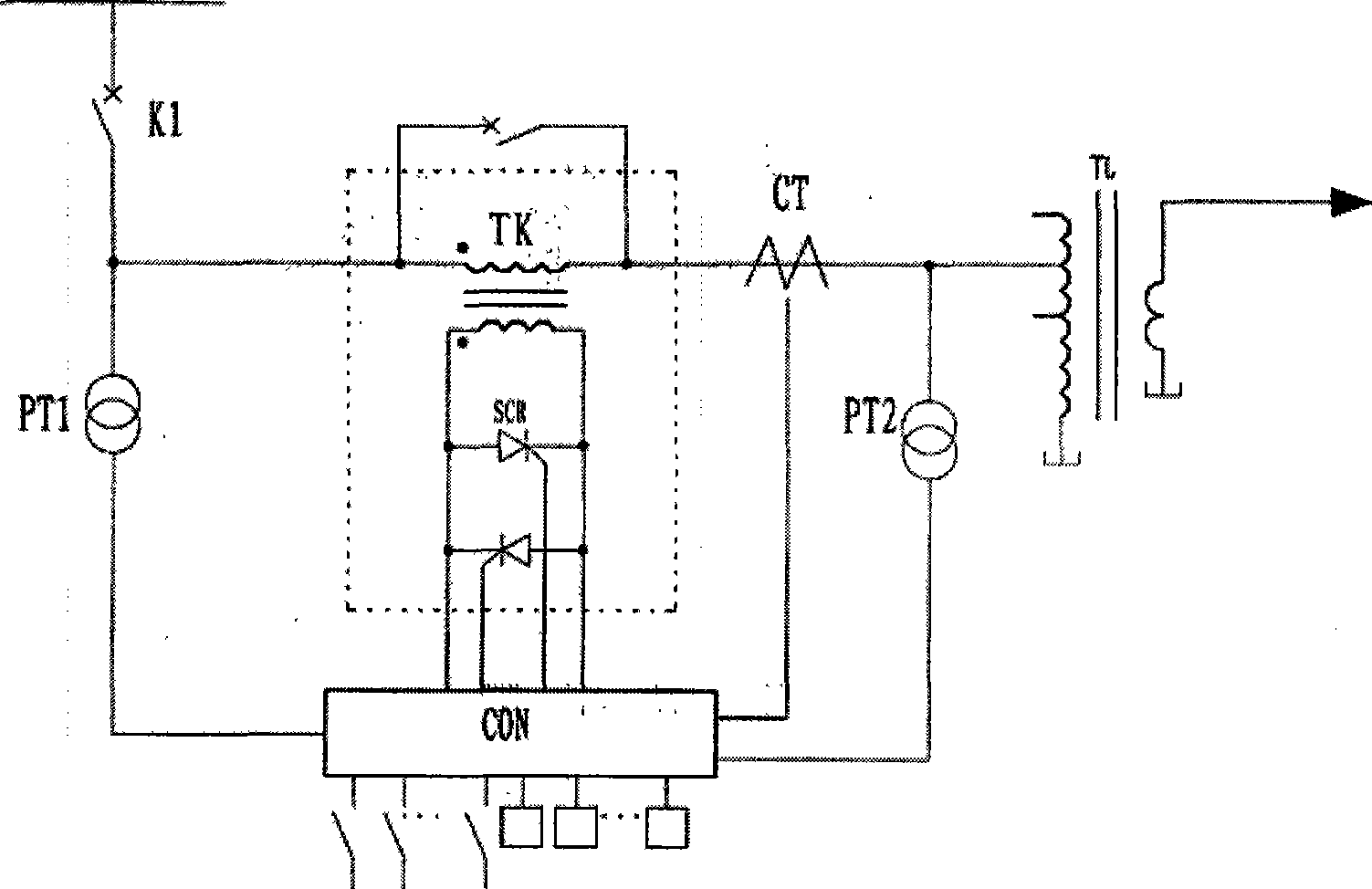
[0012] The first embodiment is suitable for low-power electric arc furnace control, such as figure 1 As shown, the starting end of the primary winding of the switching transformer TK is connected to the power supply via the circuit breaker K1, and the end is connected to the corresponding tap of the arc furnace transformer TL; both ends of the secondary winding of the switching transformer are connected to the thyristor SCR in positive and negative parallel; the main control unit circuit The phase-controlled trigger unit circuit is realized by the single-chip system CON. Its signal input terminal is connected to the current transformer CT, voltage transformer PT1 and PT2, and the output terminal is connected to the control terminal of the thyristor.

Embodiment 2

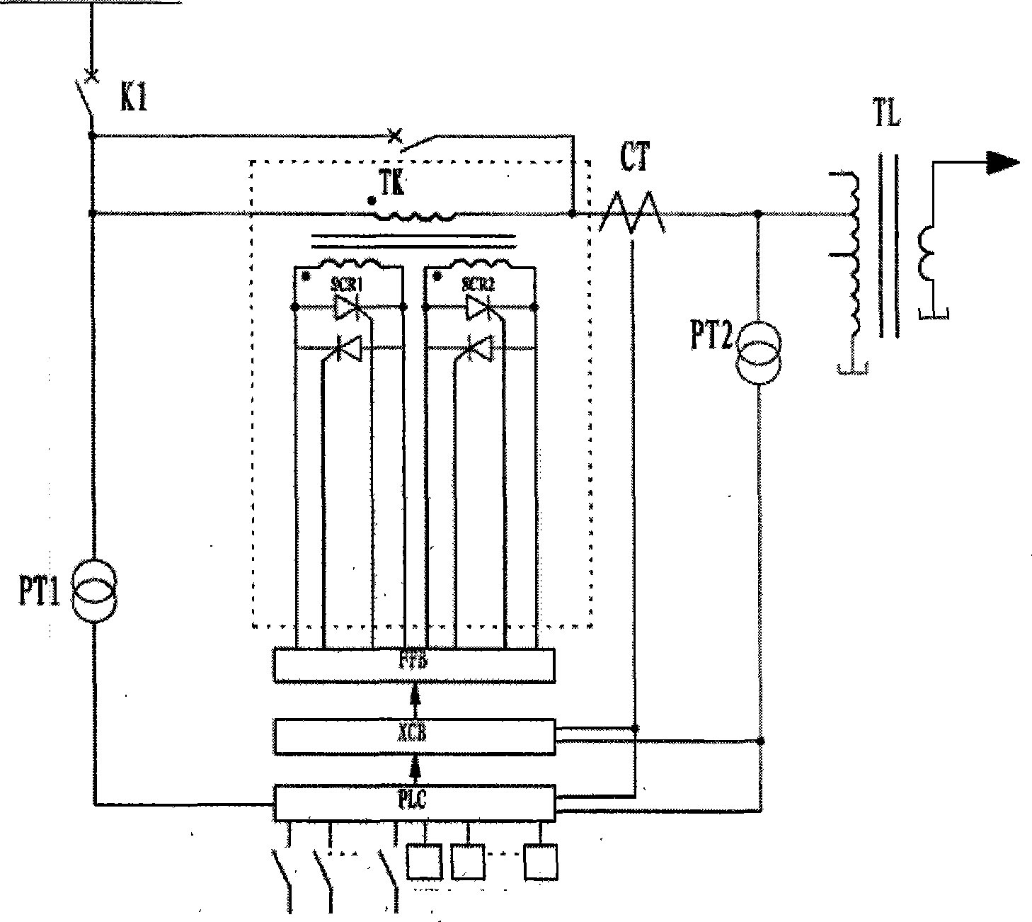
[0013] The second embodiment is suitable for the control of medium power electric arc furnace, such as figure 2 As shown, the difference from the first embodiment is: in this embodiment, the switching transformer is provided with two secondary windings for each phase, the secondary windings are independent, and the two ends of each secondary winding are connected with thyristors SCR1 and SCR2 in parallel in reverse and reverse, and the main control The unit circuit adopts programmable logic controller PLC, and the phase control trigger unit circuit adopts the phase control trigger board XCB formed by integrated circuits. The XCB signal output terminal of the phase control trigger board is connected to the amplifier circuit FFB, and the signal output terminal of the amplifier circuit is connected to the control end of the thyristor; The given input terminal of the control trigger board XCB is connected to the main control unit circuit, and the signal input terminals of the phase c...

Embodiment 3

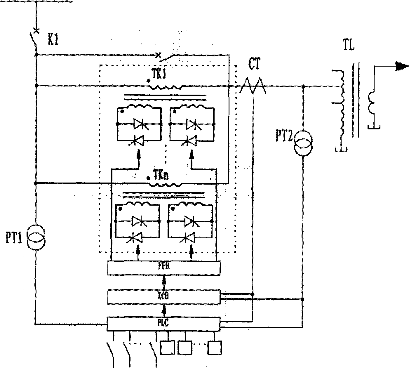
[0014] The third embodiment is suitable for high-power electric arc furnace control, such as image 3 As shown, the difference from the second embodiment is that there are multiple switching transformers TK1 to TKn. The primary windings of each transformer are connected to the same name end, one end is connected to the power supply through a circuit breaker, and the other end is connected to the corresponding tap of the arc furnace transformer. The windings are independent, and the two ends of the secondary winding are connected with thyristors connected in parallel in parallel. The effect of multiple switching transformers in parallel is to increase the control power. In principle, it is equivalent to multiple thyristors in the same direction in parallel via the leakage reactance of the switching transformer, and the current sharing effect is better, and the currents of each circuit are basically the same.

[0015] The role of the switching transformer TK in the circuit is the sam...


PUM


Abstract

The invention relates to a green energy saving electric arc furnace controlling device, which can lead that the electric arc furnace has little influence on a power system, can increase production efficiency of the electric arc furnace and reduces unit consumption. The device has the technical proposal that the green energy saving electric arc furnace controlling device is characterized in that the device is also provided with a switch transformer, a main control unit circuit and a phase-control trigger element circuit; the beginning terminal of the primary side winding of the switch transformer is connected with a power supply by a breaker while the end is connected with the corresponding tap of an arc furnace transformer; two ends of the secondary side winding of the switch transformer are connected with thyristors which are positive and negative in parallel connection. The main control unit circuit and the signal input end of the phase-control trigger element circuit are connected with a current transformator, a pressure transformator. The given input end of the phase-control triggers element circuit is connected with the output end of the main control unit circuit output. The output end of the phase-control trigger element circuit is connected with the control end of the thyristors.

Description

Technical field: [0001] The invention relates to an electric arc furnace control device. Background technique: [0002] The electric arc furnace is a smelting method in which electric energy is converted into heat in the arc by the electric arc generated by the discharge between the electrode and the charge, and the direct action of radiation and electric arc is used to heat and melt the metal and slag, and smelt various components of steel and alloys. . Heating by electric arc furnace, high temperature, high thermal efficiency, accurate temperature control, small floor space, less capital investment, and convenient operation. Therefore, the electric arc furnace steelmaking is developing rapidly, and the power of the electric arc furnace is increasing, but this kind of high power The electric arc furnace smelting also brought many problems. One of the most important problems is the large impact on the power grid, and the second is low production efficiency and high unit consumpti...

Claims


Application Information

Patent Timeline
Patent Type & Authority Applications(China)
IPC IPC(8): G05B11/01G05B19/04
Inventor 潘家忠
Owner HARBIN PATEERN SCI & TECH
Why Eureka
Try Eureka