
Part dismantling drawing system and method

A part and part numbering technology, applied in the field of parts dismantling system, can solve the problems of difficulty in guaranteeing the accuracy of dismantling part drawings and missing disassembly, and achieve the effect of improving the efficiency of dismantling drawings, saving time and labor costs

Inactive Publication Date: 2009-05-13
HONG FU JIN PRECISION IND (SHENZHEN) CO LTD +1
View PDF0 Cites 0 Cited by
  • Summary
  • Abstract
  • Description
  • Claims
  • Application Information

AI Technical Summary

Problems solved by technology

This way of dismantling the part diagram takes a lot of time to find the graphics corresponding to the assembly diagram bubbles in the disassembled part graphics, and for thousands of part molds, there is a large possibility of missing disassembly. The accuracy of the parts diagram is difficult to guarantee

Method used


Image

  • Part dismantling drawing system and method
  • Part dismantling drawing system and method
  • Part dismantling drawing system and method

Examples


Embodiment Construction

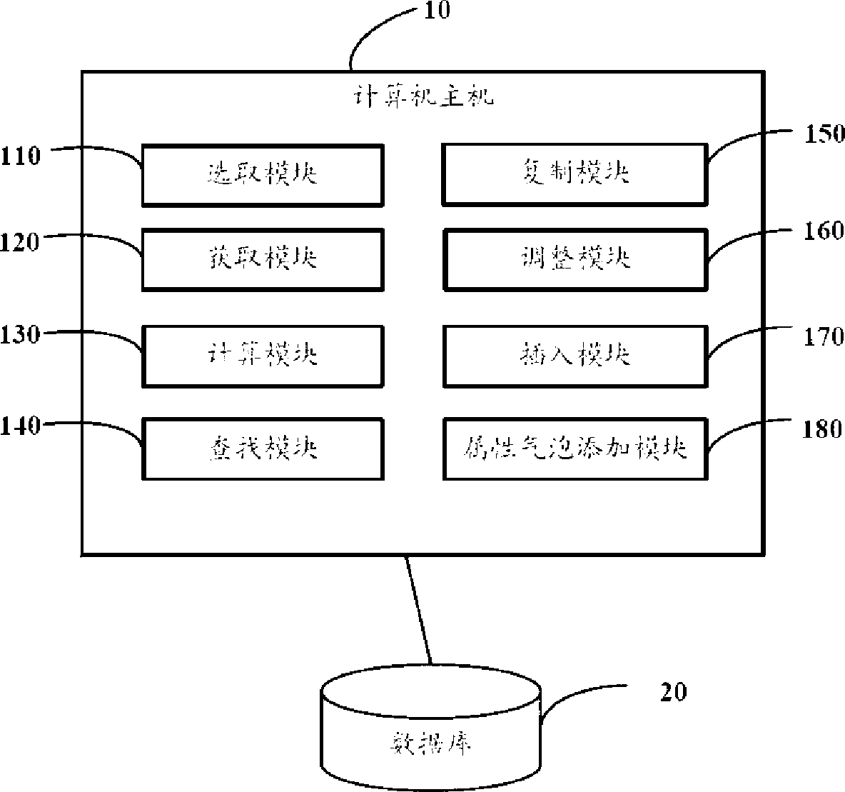
[0012] Such as figure 1 Shown is a system architecture diagram of a preferred embodiment of the parts dismantling system of the present invention. The parts dismantling system of the present invention includes a computer mainframe 10 and a database 20 connected to the computer mainframe 10. The database 20 is used to store mold assembly diagrams and main structure diagrams in mold design. The main structure diagram includes a front view, a bottom view and a right view. The mold assembly diagram is a diagram formed by taking out some required parts from the main structure diagram of the mold and combining them together. The host computer 10 mainly includes a selection module 110 , an acquisition module 120 , a calculation module 130 , a search module 140 , a copy module 150 , an adjustment module 160 , an insertion module 170 and an attribute bubble addition module 180 .

[0013] The selection module 110 is used to select the mold assembly drawings that need to be disassemble...


PUM


Abstract

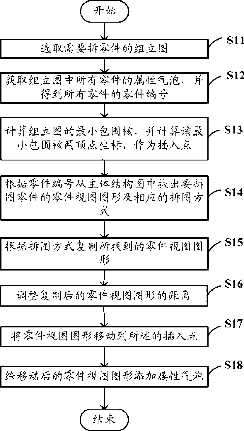
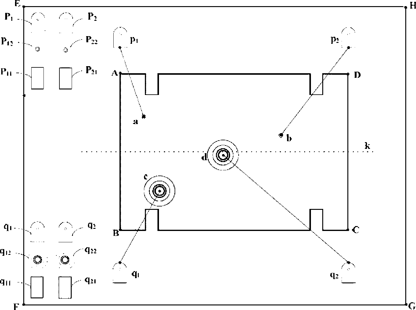
The invention provides a method for disassembling a drawing of a component. The method comprises the following steps: selecting a mould assembly drawing with the component to be disassembled from a database which also comprises a component major structure drawing; acquiring attribute bubbles of all components in the mould assembly drawing to obtain component numbers of all the components; calculating a minimum surrounding core of the mould assembly drawing, and obtaining coordinates of two peaks on the left of the minimum surrounding core as an upper insert point and a lower insert point for disassembling the drawing of the component; finding a component view graph with the drawing to be disassembled and a corresponding drawing disassembly way from the major structure drawing according to the component numbers; the component view graph found is duplicated in the drawing disassembly way; inserting the duplicated component view graph to a corresponding insert point in the mould assembly drawing. The invention also provides a component drawing disassembly system. With the invention, the component graph can be accurately disassembled to the upper part and the lower part of an assembly frame, and the efficiency for disassembling the drawing can be improved.

Description

technical field [0001] The invention relates to a system and method for dismantling drawings of parts. Background technique [0002] Manufacturing is the basis for the survival and development of human society. With the rapid development of automobiles and light industries, mold design and manufacturing have increasingly attracted people's attention, and an industry has been formed. Mold manufacturing has developed from traditional processing to two-dimensional manual programming numerical control machining, to today's CAD / CAM integrated manufacturing; mold design has also developed from manual drawing, two-dimensional computer drawing to three-dimensional computer-aided design. [0003] The biggest difficulty for mold designers in the drawing of mold assembly drawings is to disassemble the part drawings in the drawing files, that is, to disassemble the part graphics into the upper and lower parts of the assembly drawing frame according to the attribute bubble diagram of the...

Claims


Application Information

Patent Timeline
Patent Type & Authority Applications(China)
IPC IPC(8): G06F17/50G06F17/30
Inventor 常春明
Owner HONG FU JIN PRECISION IND (SHENZHEN) CO LTD
Learn More