
Video monitoring system and control method for establishing media stream transmission connection in the same

A technology of video surveillance system and streaming transmission, applied in the field of control, can solve the problems of difficult networking, difficult wiring, and large functional differences, and achieve the effect of shortening the waiting time.

Inactive Publication Date: 2009-05-13
VIMICRO CORP
View PDF0 Cites 11 Cited by
  • Summary
  • Abstract
  • Description
  • Claims
  • Application Information

AI Technical Summary

Problems solved by technology

[0003] However, the above-mentioned existing video monitoring system based on IP network has not realized full IP, especially the front-end equipment in the system is all devices not connected through IP network such as DVS and DVR, so there are the following problems:
[0004] 1. DVS, DVR and other equipment need to be connected to analog video cameras through analog cables, which makes wiring difficult and equipment maintenance costs high;
[0005] 2. The video resolution system of analog cameras, Phase Alternating Line (PAL) or National Television System Committee (National Television System Committee, NTSC) is the standard in the 1960s and 1970s, and the highest definition specified by it is Only (720×576), which hinders the development of video surveillance to high-definition video;
[0006] 3. DVS, DVR and other devices need to be connected to the video system based on their own ports, and DVR, DVS and other devices have many ports, which makes the configuration of the device more complicated, and it is difficult to realize the automatic discovery and automatic configuration functions;
[0007] 4. DVS, DVR and other equipment use the hardware board system, and the functions customized by each manufacturer are quite different, so it is necessary to formulate different access methods for the equipment of different manufacturers;
[0008] 5. DVS, DVR and other equipment have no intelligent equipment access port, which hinders the development of video surveillance to intelligent video
[0009] From the above problems, it can be seen that the existing IP network-based video surveillance system has not achieved full IP, which makes the network wiring more difficult, the system configuration is less versatile and more complex to implement, and it also hinders the development of video surveillance. Development of HD Video and Intelligence
[0010] Moreover, the existing video surveillance system based on IP network has not realized full IP, which also makes the system architecture unclear and inconsistent, and the communication protocol in the system is chaotic and irregular, and it is impossible to realize multiple video surveillance systems. Level multi-domain interconnection, so that unified management and infinite cascading expansion are impossible

Method used


Image

  • Video monitoring system and control method for establishing media stream transmission connection in the same
  • Video monitoring system and control method for establishing media stream transmission connection in the same
  • Video monitoring system and control method for establishing media stream transmission connection in the same

Examples


Embodiment Construction

[0038] In order to make the object, technical solution and advantages of the present invention clearer, the present invention will be further described in detail below with reference to the accompanying drawings and examples.

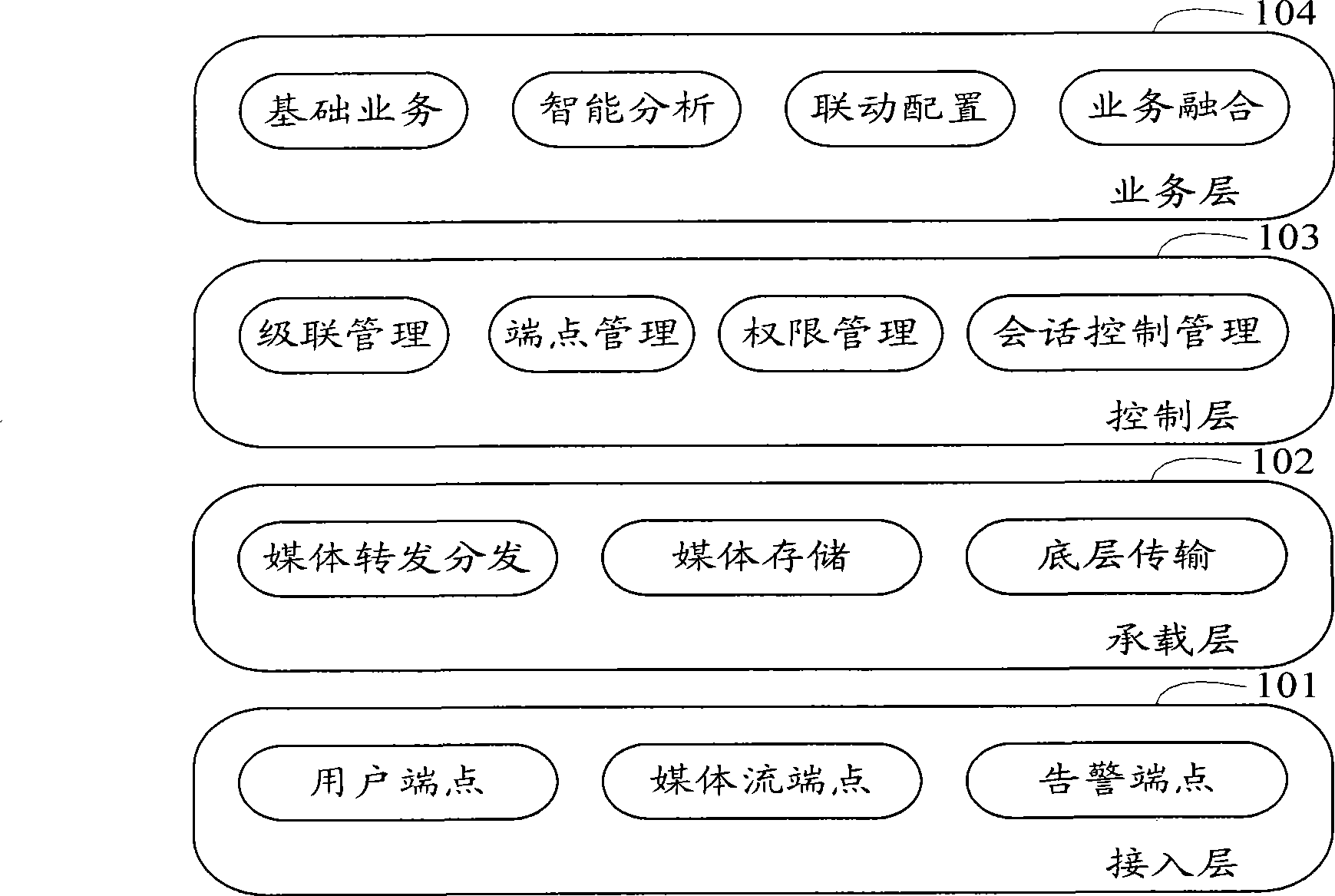
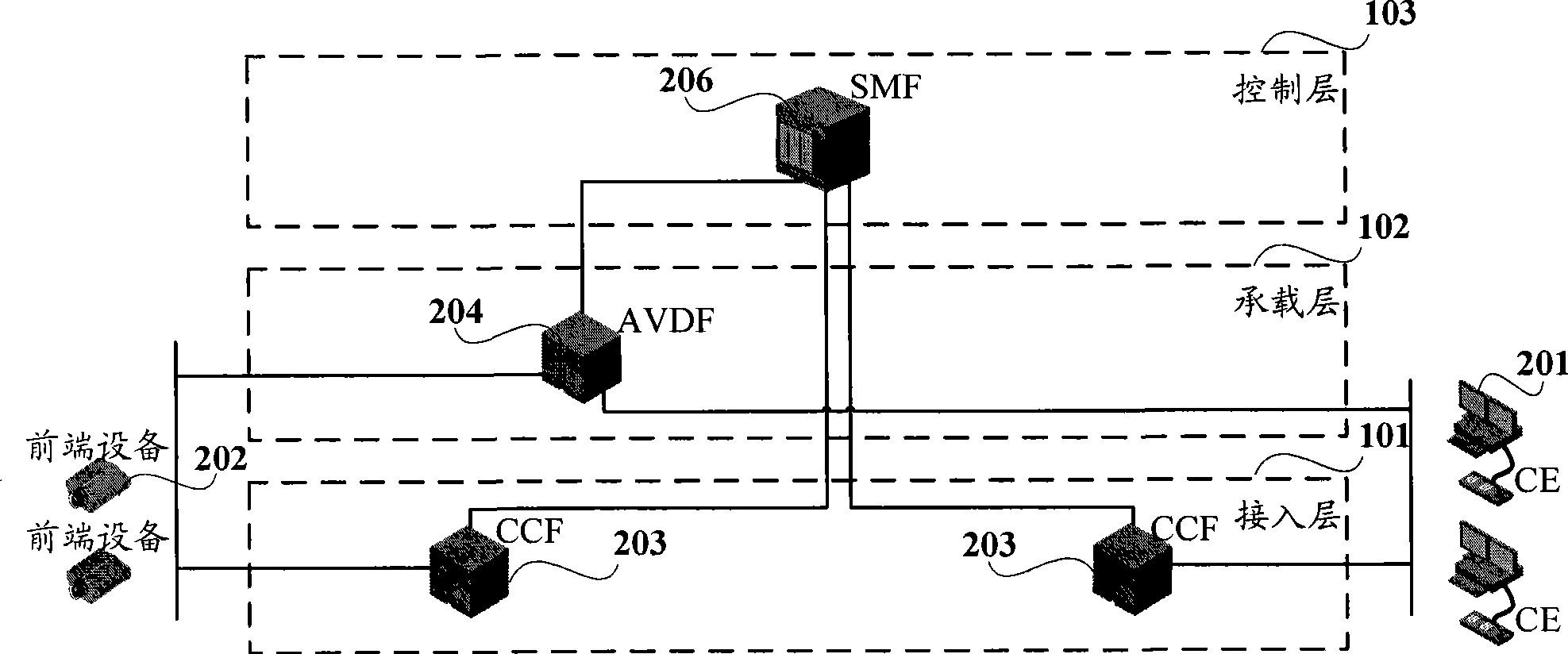
[0039] figure 1 It is a schematic diagram of the logical layer structure of the IP network-based video surveillance system in the present invention. like figure 1 As shown, in the video surveillance system based on IP network in the invention, it may include four logical layers: access layer 101 , bearer layer 102 , control layer 103 , and service layer 104 .

[0040] 1) The access layer 101 supports transmission control protocols such as IP protocol, TCP (Transmission Control Protocol, Transmission Control Protocol), UDP (User Datagram Protocol, User Datagram Protocol) and SIP (SessionInitiation Protocol, Session Initiation Protocol), for video Monitor access to various endpoints. Wherein, the endpoint may specifically include a user endpoint, a med...


PUM


Abstract

The invention discloses a video monitoring system and a control method that establishes a media stream transmission connection in the system. The invention realizes fully IP video monitoring, and can control a front device establishing media stream transmission connection with a bearing layer device at the same time registers with the front device after being accessed in the system if only a register requirement sent by the front device carrying with information for showing establishing media stream transmission connection, accordingly, only need establishing media stream transmission connection between CE and the bearing layer device without waiting media stream transmission connection between the front device and the bearing layer after CK initiating media stream transmission with the front device, so waiting time before the media stream transmission can be reduced.

Description

technical field [0001] The invention relates to control technology, in particular to a video monitoring system and a control method for establishing a media stream transmission connection in the system. Background technique [0002] The existing video monitoring system based on IP network mainly includes front-end equipment such as video monitoring camera, digital video server (Digital Video Server, DVS), digital video recorder (Digital Video Recorder, DVR), and also includes IP transmission for realizing video transmission Network, a network video monitoring platform for unified management and central storage of equipment, and a client for displaying video data on a personal computer (PC) or TV. [0003] However, the above-mentioned existing video monitoring system based on IP network has not realized full IP, especially the front-end equipment in the system is all devices not connected through IP network such as DVS and DVR, so there are the following problems: [0004] 1...

Claims


Application Information

Patent Timeline
Patent Type & Authority Applications(China)
IPC IPC(8): H04N7/18H04L29/06
Inventor 李海菊
Owner VIMICRO CORP
Learn More