
Continuous track raking loader

A rake loader and crawler technology, which is applied in the field of continuous crawler rake loader, can solve the problems of discontinuous work of the rake bucket rock loader, high labor intensity of workers, and inability to use thin coal seams, etc., and achieves wide practicability, compact structure, and convenience. The effect of loading and conveying

Inactive Publication Date: 2009-05-20
CHINA UNIV OF MINING & TECH
View PDF0 Cites 5 Cited by
  • Summary
  • Abstract
  • Description
  • Claims
  • Application Information

AI Technical Summary

Problems solved by technology

[0002] At present, coal mine underground roadway excavation is divided into general mechanized excavation and comprehensive mechanized excavation. Due to the high cost of excavation machine in comprehensive mechanization, and the current level of technical level of excavation machine for hard rock is low, the consumption of picks is relatively large. Therefore, blasting excavation In coal mine roadway excavation, it still occupies a considerable proportion in our country, and the coal excavated by guns is transported out by manual shoveling to the conveyor, which is labor-intensive for workers; However, due to the non-continuous operation of the rake bucket rock loader, the high body, low work efficiency, and it cannot be used in thin coal seams, there is an urgent need for a continuous type that integrates loading and transportation, is easy to use, has good safety performance, and has high efficiency. High and low labor intensity equipment suitable for continuous loading and transportation of thin coal seams

Method used


Image

  • Continuous track raking loader
  • Continuous track raking loader
  • Continuous track raking loader

Examples


Embodiment Construction

[0011] The present invention will be further described below in conjunction with the embodiment in the accompanying drawings:

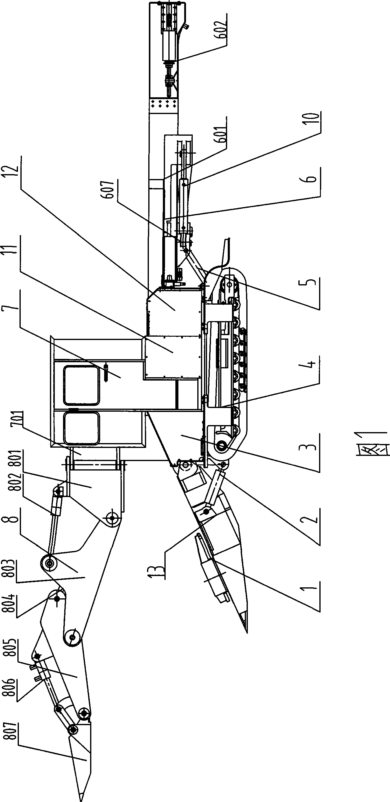
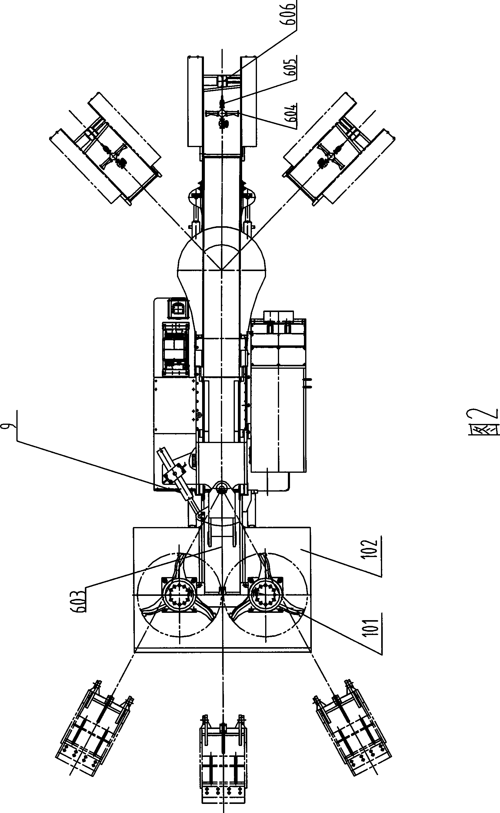
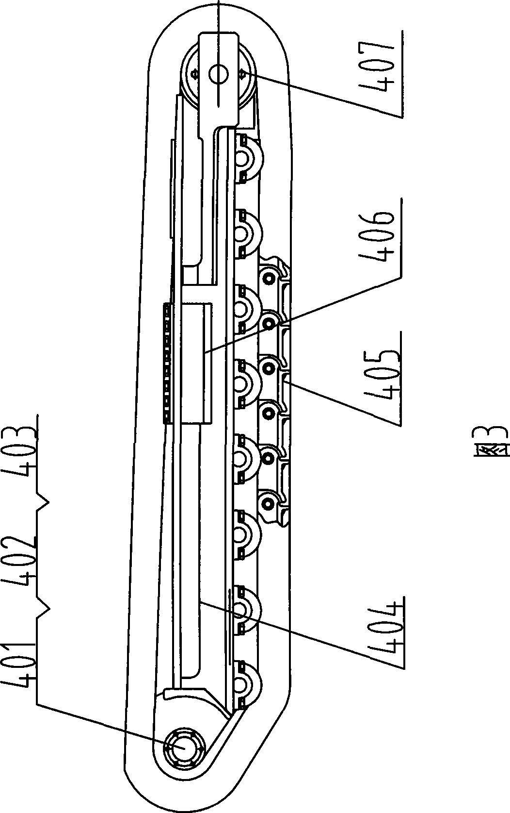
[0012] As shown in the accompanying drawings, the main engine is mainly composed of a driving device 3, a traveling device 4 and a cab 7, and its height is lower than 2 meters. The driving device 3 and the cab 7 are installed above the traveling device 4, and the cab 7 is installed on the driving device. 3 on. The loading part 1 is installed under the front part of the main engine. The loading part 1 is mainly composed of a scraping plate 102 and two star wheels 101 symmetrically arranged on the scraping plate 102. The tail end of the scraping plate 102 is connected with the driving device 3. The two sides of the car are connected with the loading part lifting cylinder 2 fixed on the main frame, and the loading part 1 can swing up and down + 300-200mm around the pin shaft. The loading part 1 is hingedly installed on the front end of the driving devic...


PUM


Abstract

A continuous caterpillar rake loader is composed of a drive device, a running gear and a conveying device; a scraper bucket device is arranged above the front of a main machine, articulated on a gantry of a driving cab and connected with a swing hydraulic cylinder that is fixed on a main frame; the lower part of a conveying device is connected with a hoist cylinder fixed on the main frame, the bottom of the conveying device is provided with a swing cylinder which can lead the conveying device to swing left and right; a pumping station is respectively connected with a star-wheel-drive motor of a loading part, a running motor of the running gear, the hoist cylinder of the loading part, the swing cylinder of the scraper bucket device, the hoist cylinder and the swing cylinder of the conveying device; and the outside of an electrical cabinet is provided with a flameproof casing. The rake loader completes rake loading of materials simultaneously when loading materials, thus realizing continuous loading, improving loading efficiency and the reliability of the loading part, being applicable to continuous rake loading of low coal seam in coal mine as well as to the places in need of rake loading on the ground; and the rake loader is compact in structure, convenient in operation, high in reliability, multi-purpose with one machine, and small in the size of the machine body.

Description

technical field [0001] The invention relates to a continuous crawler raking machine, which is especially suitable for continuous raking of thin coal seams in coal mines, and also suitable for occasions where continuous raking is required on the ground. Background technique [0002] At present, coal mine underground roadway excavation is divided into general mechanized excavation and comprehensive mechanized excavation. Due to the high cost of excavation machine in comprehensive mechanization, and the current level of technical level of excavation machine for hard rock is low, the consumption of picks is relatively large. Therefore, blasting excavation In coal mine roadway excavation, it still occupies a considerable proportion in our country, and the coal excavated by guns is transported out by manual shoveling to the conveyor, which is labor-intensive for workers; However, due to the non-continuous operation of the rake bucket rock loader, the high body, low work efficiency...

Claims


Application Information

Patent Timeline
Patent Type & Authority Applications(China)
IPC IPC(8): B65G65/10E21F13/00
Inventor 李建平杜长龙蔡津玲赵武丁开旭徐龙江刘送永王清华
Owner CHINA UNIV OF MINING & TECH
Learn More