

Method for removing pollutant in oil
A pollutant and hollow technology, applied in the field of removing pollutants in oil, can solve the problems of blackening of oil color and decline of oil quality
- Summary
- Abstract
- Description
- Claims
- Application Information
AI Technical Summary
Problems solved by technology
Method used
Image

Examples
Embodiment 1
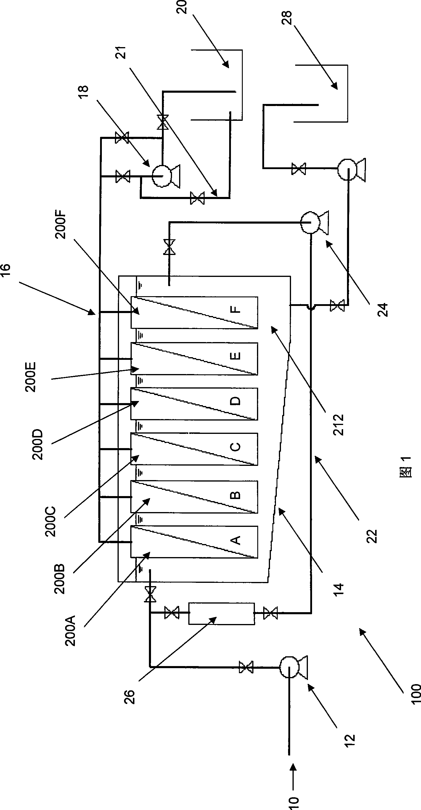
[0114] In this example, the waste motor oil was maintained at a temperature of 50°C and operated continuously, with an interruption of 1 hour after every 11 hours. During the 1 hour break, the membrane pump 18 on the permeate line 16 was turned off to allow the membrane to settle for a period of time.
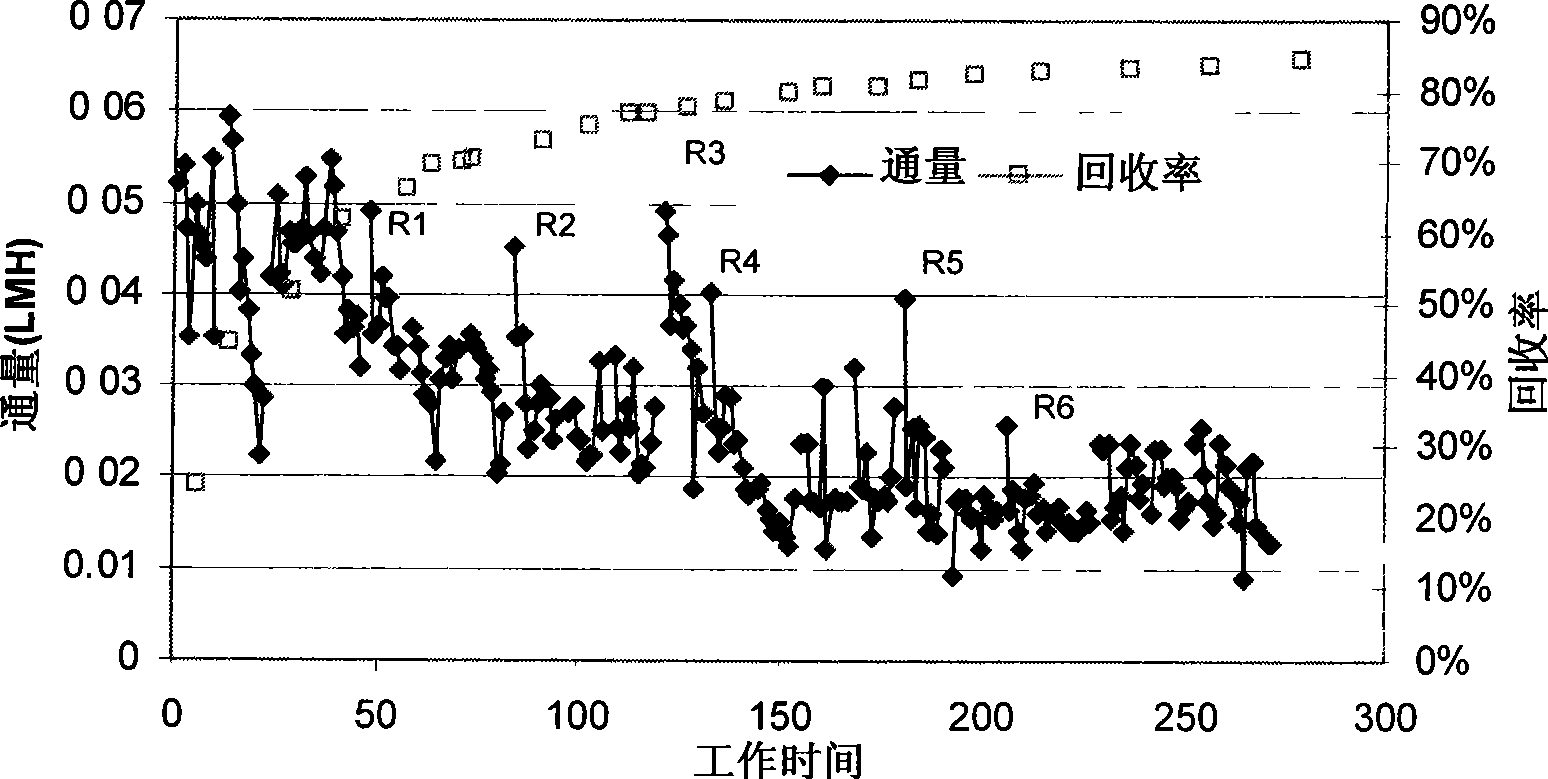
[0115] Circulation rate and recovery over time in image 3 shows that the relationship between circulation rate and recovery is in Figure 4 displayed in .
[0116] from image 3 with Figure 4 It can be seen that the flux generally decreases linearly with the increase of the recovery rate. It can also be seen that the flux increases after the membrane is left for a period of time, as shown by the data lines R1, R2, R3, R4, R5, R6.
[0117] During continuous operation of the system 100, a layer of oil with a higher viscosity and higher contaminant content forms on the surface of the membrane fibers. This prevents oil from passing through the membrane, adversely affecting ...
Embodiment 2
[0119] In this example, the spent motor oil was maintained at 32-34 degrees Celsius and run for 12 hours per day. The method used to regenerate the membrane flux is through oil backwash.
[0120] When the flux drops below 0.02LMH, backwash the permeate oil to regenerate the flux of the membrane. During this process, permeate oil is pumped through the membrane from the permeate side of the membrane at a pressure of +1.5 bar. Oil backwashing was performed for 30 minutes each time.
[0121] Circulation rate and recovery over time in Figure 5 displayed in . It can be seen that as the flow rate increases with time, the recovery decreases. It can also be seen that the flow rate increases after permeate oil backwash, indicating that oil backwash is suitable for maintaining relatively high membrane flux.
[0122] However, oil backwashing requires the use and consumption of penetrating oil, which is uneconomical. Also, over a long period of time, the average production rate will...
Embodiment 3
[0124] In this example, the spent motor oil was maintained at 50°C and operated continuously, combined with a 30 minute period of membrane regeneration after every 5.5 hours. During membrane regeneration, an oil backwash was performed for 10 minutes, followed by a 20 minute membrane rest period.
[0125] Circulation rate and recovery over time in Image 6 The relationship between flow rate and recovery is shown in Figure 7 displayed in .
[0126] The combined membrane regeneration method showed good performance as it combined the advantages of both oil backwash and membrane rest periods. Shorter oil backwashing consumes less permeate oil while removing contaminants that clog the membrane pores, and the membrane sits for a period of time so that the thicker oil layer with higher viscosity and higher contaminant content around the membrane surface is reduced .
[0127] As a result, the combined method shows much better performance than either method by itself.
PUM
 Abstract
Description
Claims
Application Information