Substrate processing apparatus and substrate processing method

a substrate processing and substrate technology, applied in the direction of cleaning process and apparatus, chemistry apparatus and process, cleaning liquid, etc., can solve the problems of large liquid consumption, particle contamination of cleaning liquid, arm collision with spin chuck,

Inactive Publication Date: 2002-07-25
TOKYO ELECTRON LTD
View PDF11 Cites 76 Cited by
  • Summary
  • Abstract
  • Description
  • Claims
  • Application Information

AI Technical Summary

Problems solved by technology

In such cleaning apparatus, a cleaning liquid is continuously fed to a wafer on rotation, and accordingly a liquid consumption is large.
A height of the support pins are made accordingly low, with a resultant risk that when the arm of the carriage means transfers a wafer to and from the support pins, the arm may collide with the spin chuck.
In a case that the upper side member is directly contacted to the cleaning liquid, when particles, etc. stay on the upper side member, there is a risk that the particles may contaminate the cleaning liquid.
On the other hand, in the substrate cleaning apparatus, in a case that the support pins are made high for the prevention of the collision of the spin chuck, a cleaning liquid puddle which fills the gap between the wafer and the spin chuck cannot be formed.
And also, in the case that the support pins are made high, a prescribed amount of the cleaning liquid must be continuously fed with the wafer being rotated as required, which causes a problem that a consumption of the cleaning liquid is increased.

Method used


Image

  • Substrate processing apparatus and substrate processing method
  • Substrate processing apparatus and substrate processing method
  • Substrate processing apparatus and substrate processing method

Examples


example

[0113] The present invention was tested. Removal amounts (etching rates) of the puddle cleaning which puddles a cleaning liquid on a wafer W to clean the wafer W will be evaluated.

[0114] First, as shown in FIG. 21, an about 10 nm.+-.0.3 nm thermal oxide film (Th-Oxide) was formed on a wafer, and the wafer W was placed on a mount 101 with a heater 10 buried in. A cleaning liquid heated to a prescribed temperature (e.g., 60.degree. C.), e.g., APM(NH.sub.4OH / H.sub.2O.sub.2 / H.sub.2O mixed liquid) was puddled on the thermal oxide film, and the wafer was subjected to SCI puddle cleaning at the room temperature. Mixed content ratios of the APM components, i.e., an aqueous solution of ammonium (NH.sub.4OH) : aqueous hydrogen peroxide (H.sub.2O.sub.2) : pure water (H.sub.2O) were changed sequentially, e.g., from 1:1:5, 1:1:10, 1:2:5, 1:2:10, 1:5:5, 1:5:10, 1:5:20 to 1:5:50 to investigate changes of removal amounts of the thermal oxide film. The film thickness was measured by an optical film ...


PUM


Abstract

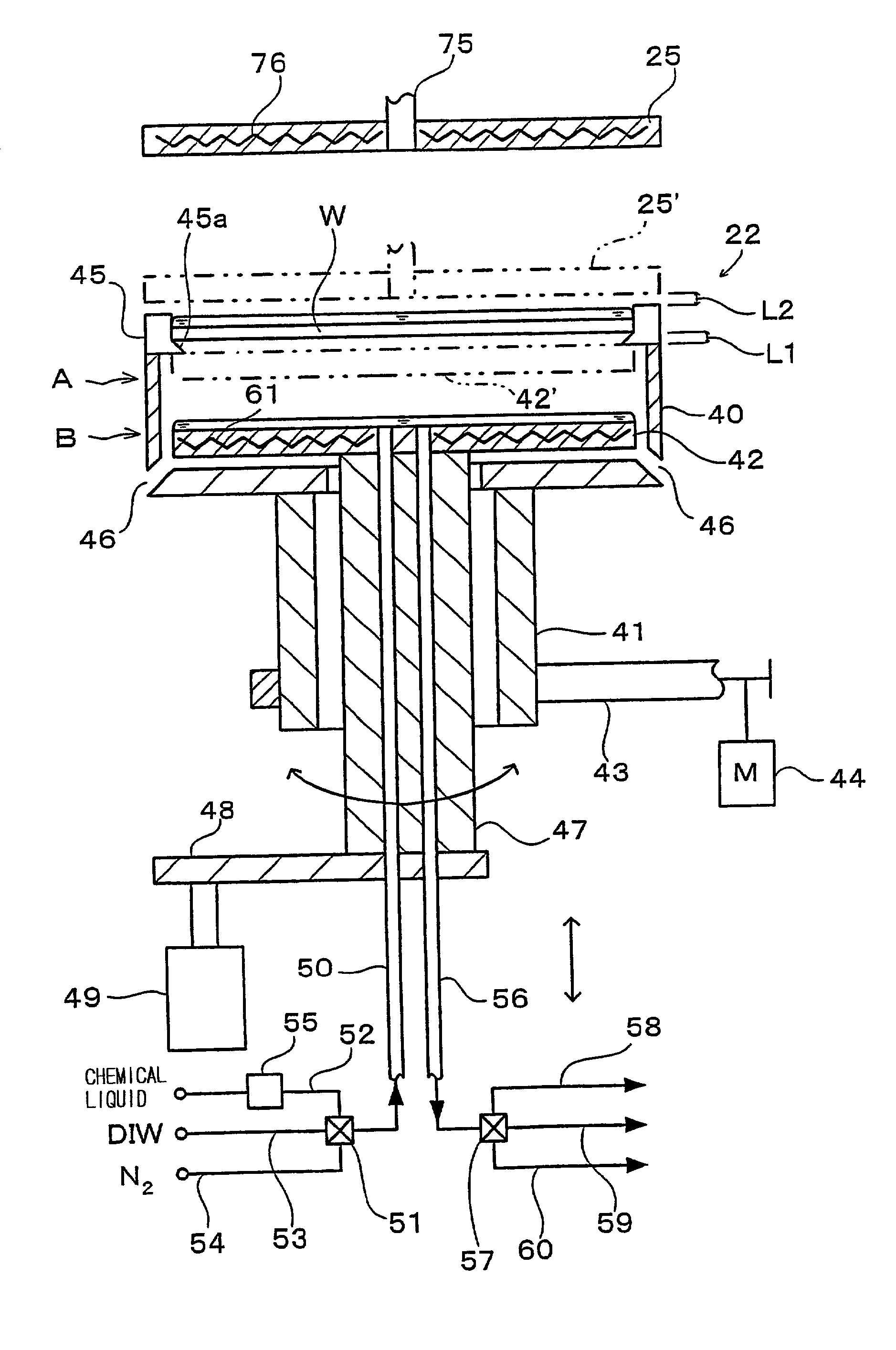
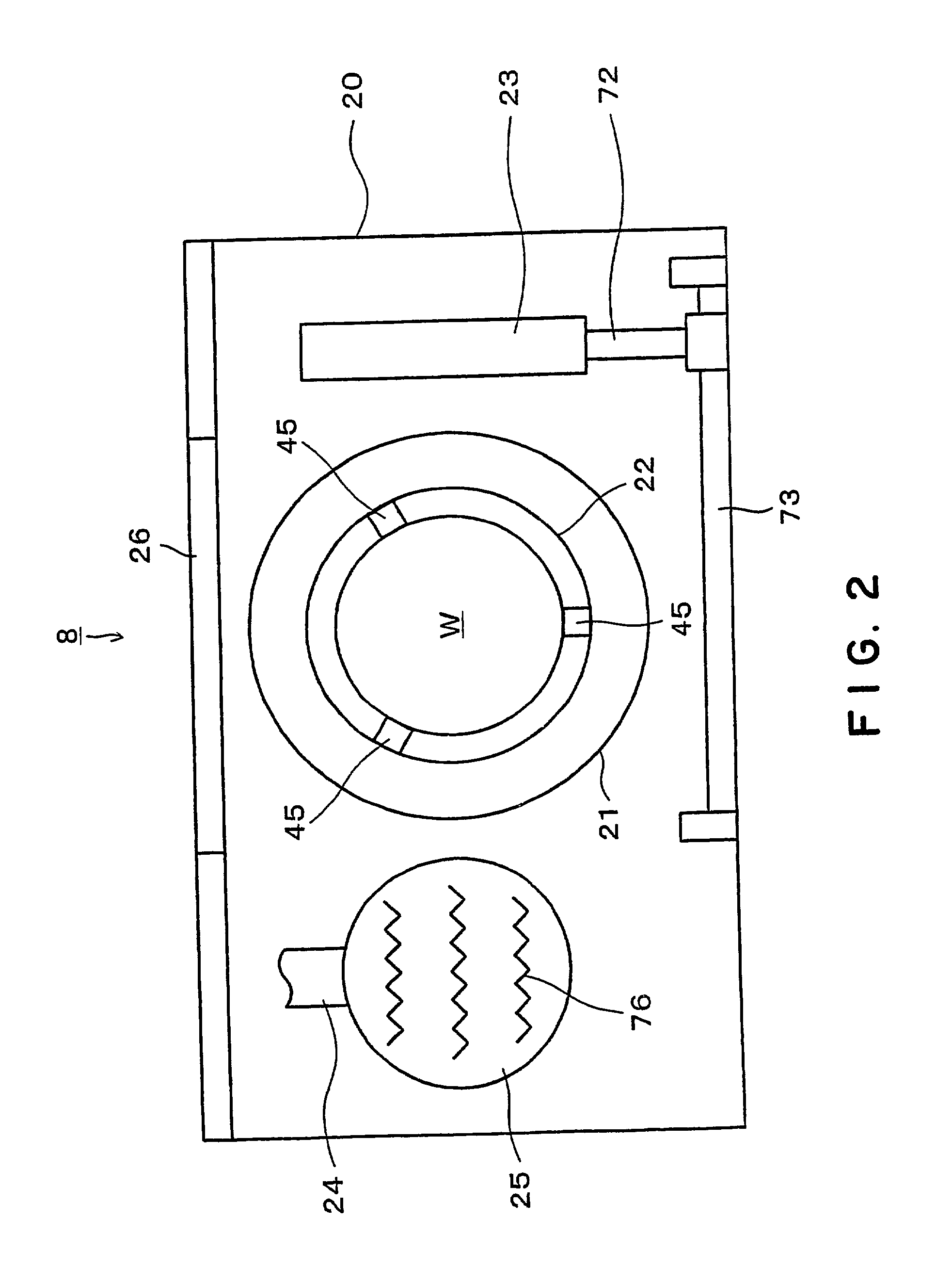
A substrate processing apparatus 8 for feeding a processing liquid and processing a substrate W with the processing liquid comprises holding member 22 for holding the substrate W, and a lower side member 42 which is moved relatively with respect to the back surface of the substrate W held by the holding member 22 between a processing position A near the substrate undersurface and a retreat position B remote from the substrate undersurface. The processing liquid is fed between a gap between the lower side member 42 moved to the processing position A and the back surface of the substrate held by the holding member 22, and the substrate undersurface is processed. A cleaning processing unit 221a as one embodiment of the liquid processing apparatus comprises a spin chuck 22 for holding a wafer W substantially horizontally, a stage 224 substantially horizontally below the wafer W held by the spin chuck 223, and a cleaning liquid discharge openings 241 for feeding a required cleaning liquid into a gap between the wafer W held by the spin chuck 223 and the stage 224. The stage 224 has the surface coated with a hydrophobic polymer so that the surface has wetting which allows a contact angle of the cleaning liquid to be above 50E. A layer of the cleaning liquid is formed in the gap between the wafer W held by the spin chuck 223 and the stage 224 to subject the wafer W to the liquid processing.

Description

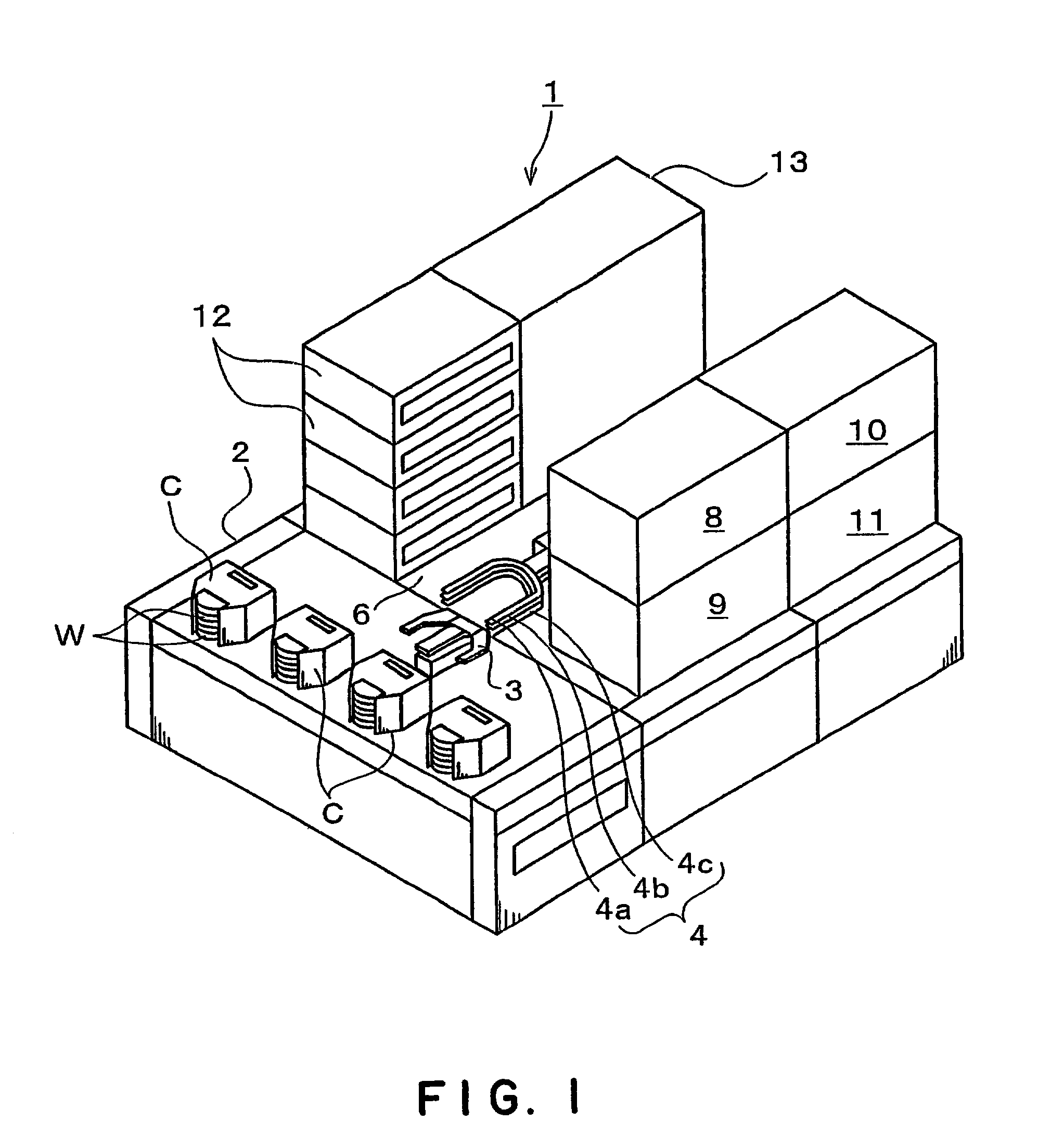
[0001] The subject application is related to subject matter disclosed in Japanese Patent Application No. 2001 -15027 filed on Jan. 23, 2001 and Japanese Patent Application No. 2001 -150283 filed on May 21, 2001 in Japan to which the subject application claims priority under Paris Convention and which are incorporated herein by reference.[0002] 1. Field of the Invention[0003] The present invention relates to a substrate processing apparatus for cleaning substrates, such as semiconductor wafers, LCD glass substrates, etc., and a substrate cleaning method. The present invention relates also to a liquid processing apparatus (processing apparatus) for making liquid processing, as of cleaning, etc., on semiconductor wafers, LCD substrates, etc., and a liquid processing method (processing method).[0004] 2. Related Background Art[0005] Semiconductor device fabrication processes, for example, use cleaning systems for cleaning semiconductor wafers (hereinafter called "wafers") with chemical l...

Claims


Application Information

Patent Timeline
Patent Type & Authority Applications(United States)
IPC IPC(8): H01L21/304B08B3/04B08B3/10H01L21/00
CPCB08B3/04B08B3/10H01L21/67051H01L21/67103H01L21/304
Inventor TOSHIMA, TAKAYUKIORII, TAKEHIKO
Owner TOKYO ELECTRON LTD
Why Eureka
Try Eureka