Automatic feeding device of engine fuel

An automatic supply and engine technology, applied in the directions of oil supply device, engine components, engine control, etc., can solve the problem of high cost of transformation, and achieve the effect of improving work efficiency, simple manufacturing and reasonable structure

Inactive Publication Date: 2009-05-20
牟利民
View PDF0 Cites 5 Cited by
  • Summary
  • Abstract
  • Description
  • Claims
  • Application Information

AI Technical Summary

Problems solved by technology

[0003] In order to overcome the disadvantages in the prior art that the components of the fuel supply system need to be modified and replaced by using different fuels, the modification cost is high, and the fuel supply device can only use one kind of fuel, the present invention provides an automatic fuel supply device for engines

Method used


Image

  • Automatic feeding device of engine fuel
  • Automatic feeding device of engine fuel

Examples


Embodiment Construction

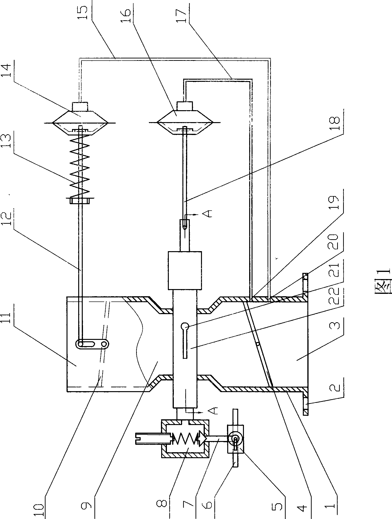
[0010] As shown in Figure 1, an automatic fuel supply device for an engine includes a mixer body (1) and a fuel control valve (5), and the two ends of the mixer body (1) are respectively provided with air inlets (11 ) and the mixed fuel outlet (3), a mixing chamber (9) is between the body inlet (11) and the mixed fuel outlet (3) of the mixer, and a mixing chamber (9) is provided at the end of the mixed fuel outlet (3) The installation hole (2) is connected, a choke valve (10) is installed on the air inlet (11), and a throttle valve (4) is installed on the mixed fuel outlet (3). When in use, the air inlet (11) of the mixer is assembled with the air filter, and the mixed fuel outlet (3) is sealed and connected with the air intake pipe of the engine cylinder through the connecting mounting hole (2).

[0011] In Fig. 1, the fuel control valve (5) is a conversion type control valve, and the conversion type fuel control valve is respectively provided with two fuel input ports (6) an...


PUM


Abstract

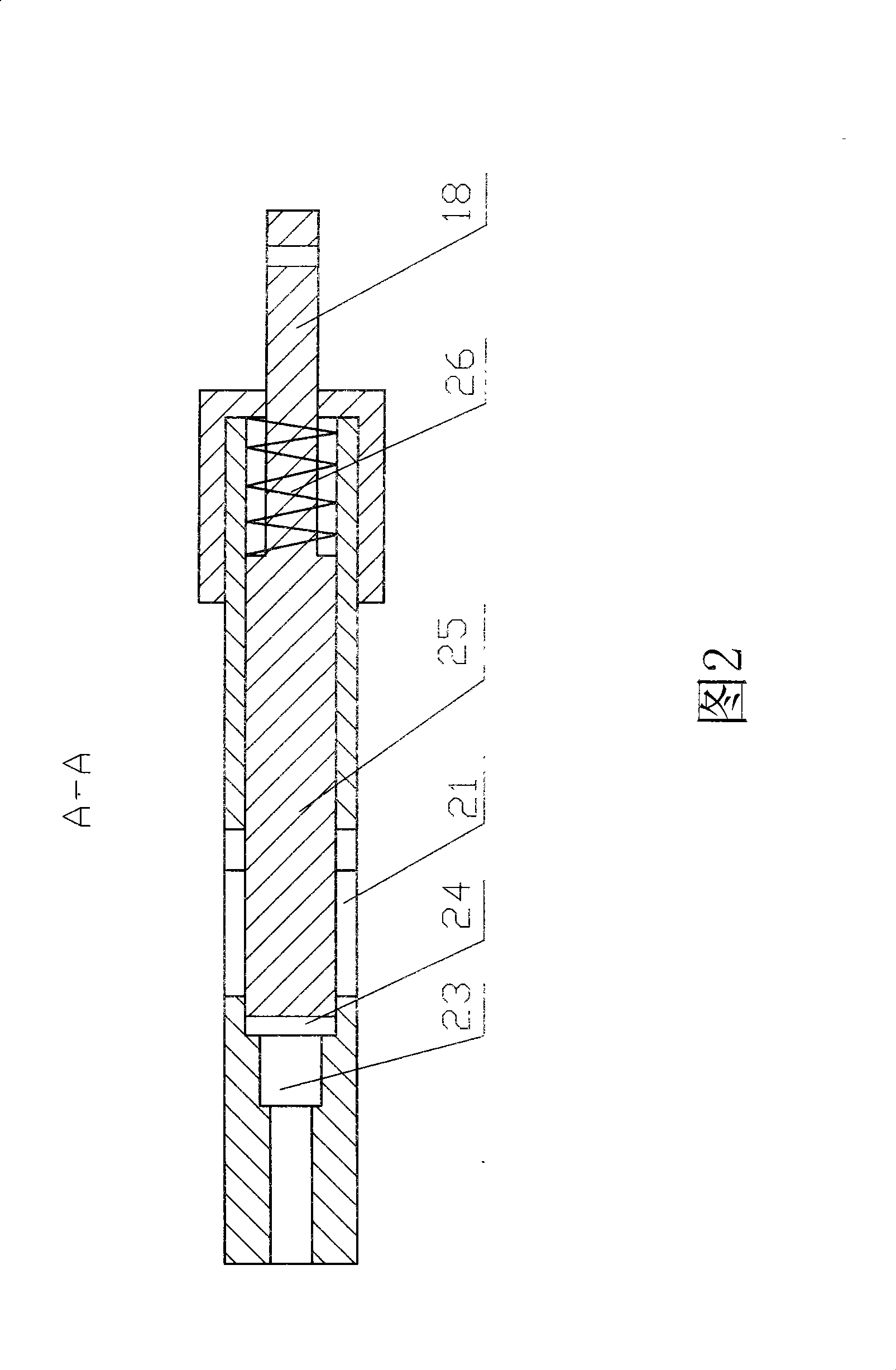
The invention relates to an engine fuel automatic feeding device which comprises a mixer and a fuel control valve. The mixer consists of a gas inlet, a mixing chamber and a mixed fuel outlet, wherein a chock valve is arranged on the gas inlet; and a throttle is arranged on the mixed fuel outlet. The device is characterized in that the fuel control valve is a change-over valve which has an input port for different fuels and a fuel output port; the fuel output port is communicated with a pressure regulation valve communicated with a fuel chamber of a fuel distribution valve; a plunger cavity communicated with the fuel chamber is arranged on the distribution valve; the cavity wall is provided with a fuel outlet which is arranged inside the mixing chamber; a plunger is arranged in the plunger cavity; the motion of the plunger controls the opening and closing of the fuel outlet; two vacuum holes are reserved on the mixer body outside the throttle, and are communicated with vacuum valves through communication pipes respectively; the execution end of one vacuum valve controls the opening and closing of the chock valve; and the execution end of the other vacuum valve controls the motion of the plunger. The engine fuel automatic feeding device can automatically adjust the air-fuel ratio, the mixed gas intake and the supply of different fuels.

Description

technical field [0001] The invention relates to the supply of combustible mixture for general combustion engines, in particular to an automatic fuel supply device for engines that can supply gasoline, liquefied petroleum gas and natural gas with the same device. Background technique [0002] At present, known gasoline engines can be divided into electronic injection engines and carburetor engines, and their fuel supply systems all change gasoline from liquid to mist and then supply the engine. Among them, the electronic injection engine fuel supply system has high work efficiency but high manufacturing cost; the carburetor type engine fuel supply system has low manufacture cost but has the disadvantage of low work efficiency. When the above-mentioned two gasoline engines use natural gas or liquefied petroleum gas without changing the compression ratio of the original engine, the components of the fuel supply system need to be replaced and modified, which has the disadvantage...

Claims


Application Information

Patent Timeline
Patent Type & Authority Applications(China)
IPC IPC(8): F02D33/00F02M1/08F02M21/02
CPCY02T10/32
Inventor 牟利民
Owner 牟利民
Why Eureka
Try Eureka