Hydraulic unit, castor assembly and container moving device and method

A hydraulic unit and container technology, applied in fluid pressure actuating devices, servo motor components, packaging, etc., can solve the problems of unsuitable container moving devices, occupancy of yoke frame 3 and frame 7, potential safety hazards, etc., and achieve space improvement The effect of utilization rate, compact structure and easy maintenance

Inactive Publication Date: 2009-05-20
CHINA INTERNATIONAL MARINE CONTAINERS (GROUP) CO LTD
View PDF0 Cites 4 Cited by
  • Summary
  • Abstract
  • Description
  • Claims
  • Application Information

AI Technical Summary

Problems solved by technology

[0003] Since the hydraulic cylinder 5 is electrically driven and needs to be connected to the power supply unit B through the cable 2, the movement of the power supply unit B must be considered when moving the container, and the operation is complicated
In addition, when moving, it is also necessary to ensure the reliable connection of the cable 2 and avoid the winding or wear of the cable 2, so there are certain potential safety hazards
In addition, although compared with large mechanical equipment such as forklifts and spreaders, figure 1 The volume of the shown device is relatively small and exquisite, yet the yoke frame 3 and the frame 7 still take up a large space
Therefore, for places where the space is relatively narrow, this container moving device is not suitable

Method used


Image

  • Hydraulic unit, castor assembly and container moving device and method
  • Hydraulic unit, castor assembly and container moving device and method
  • Hydraulic unit, castor assembly and container moving device and method

Examples


Embodiment Construction

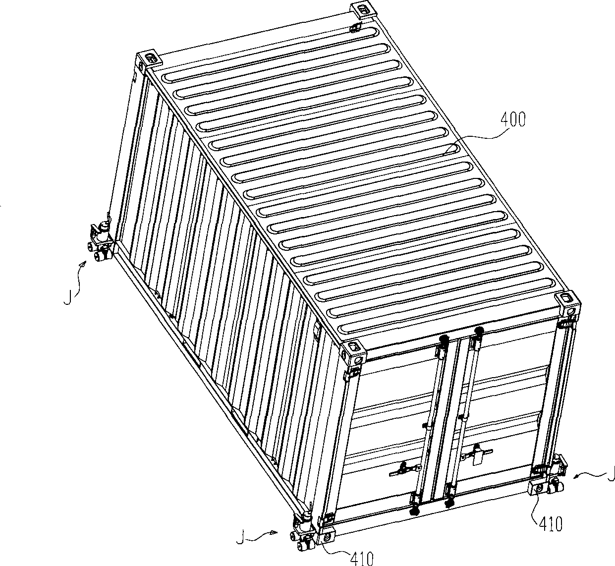
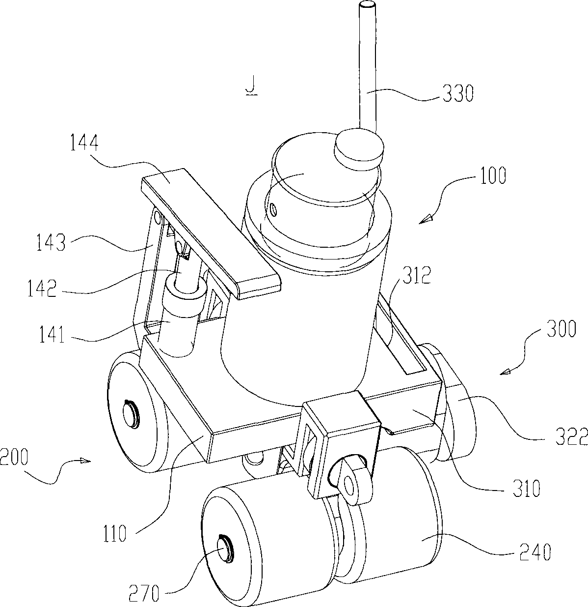
[0032] like figure 2 As shown, the container moving device of the present invention includes four caster assemblies J. Each caster assembly J can be connected to a bottom corner piece 410 of the container 400 respectively. like image 3 As shown, each caster assembly J includes a hydraulic unit 100, a traveling unit 200 for moving, and a positioning tightening mechanism 300 for cooperating with the bottom corner fittings of the container.

[0033] like Figure 3-11 As shown, the hydraulic unit 100 includes a hydraulic mechanism 120 , an oil tank 130 and a foot pump 140 respectively disposed on the support base 110 . Wherein, the pump body 141 of the pedal pump 140 communicates with the oil cylinder 121 of the hydraulic mechanism through the oil supply circuit, and the oil supply check valve 50 is arranged in the oil supply circuit, so that the hydraulic oil can only flow from the pump body one-way. 141 flows to the oil cylinder 121; the oil tank 130 communicates with the ...


PUM


Abstract

The invention discloses a hydraulic unit, a trundle component with the hydraulic unit, a device utilizing the trundle component to move a container and a method thereof. The hydraulic unit comprises a hydraulic mechanism, an oil tank, a foot pump, a supporting seat, an oil supply passage, an oil suction passage and an unloading oil passage, wherein the hydraulic mechanism comprises an oil cylinder and a piston arranged in the oil cylinder; the oil tank circles the oil cylinder and is used for accommodating hydraulic oil; the foot pump comprises a pump body and a pump core arranged in the pump body; the supporting seat is used for fixing the hydraulic mechanism, the oil tank and the foot pump; the oil supply passage is communicated with the pump body and the oil cylinder; the oil suction passage is communicated with the oil tank and the pump body; and the unloading oil passage is communicated with the oil cylinder and the oil tank. The hydraulic unit is provided with the foot pump, so the hydraulic unit can drive the hydraulic mechanism to work without needing external equipment in order that the hydraulic unit has a compact integral structure and convenient operation.

Description

technical field [0001] The present invention relates to a hydraulic unit, in particular to a hydraulic unit having a hydraulic mechanism comprising a cylinder and a piston which can extend downward along the axis of the cylinder, and a caster assembly having said hydraulic unit, as well as a container moving device and method. Background technique [0002] In the prior art, large mechanical equipment such as forklifts and spreaders are usually used to move containers. However, such a large-scale device itself has disadvantages such as a large volume, a large space required for work, and a limited range of movement. For containers with bottom corner fittings, there is currently a container moving device. like figure 1 As shown, this container moving device includes four lifting assemblies A. Each lifting assembly A includes a C-shaped yoke frame 3 that can cooperate with a container D, wheels 20, a hydraulic cylinder 5 arranged between the yoke frame 3 and the wheels 20, ...

Claims


Application Information

Patent Timeline
Patent Type & Authority Applications(China)
IPC IPC(8): F15B15/18F15B15/14F15B13/02F15B11/16B65D90/18
Inventor 周立杰周平辉张巍
Owner CHINA INTERNATIONAL MARINE CONTAINERS (GROUP) CO LTD
Why Eureka
Try Eureka