Method for testing power cable fault based on secondary pulse mode

A power cable and sub-pulse technology, applied in the field of power cable fault detection, can solve problems such as difficult to grasp, many interference components, complex high-voltage pulse reflection waveforms, etc., and achieve the effect of large volume, strong identification and small volume

Inactive Publication Date: 2009-05-20
西安四方机电有限责任公司
View PDF0 Cites 30 Cited by
  • Summary
  • Abstract
  • Description
  • Claims
  • Application Information

AI Technical Summary

Problems solved by technology

The high-voltage pulse reflection waveform at the fault point is often complex, with many interferen...

Method used


Image

  • Method for testing power cable fault based on secondary pulse mode
  • Method for testing power cable fault based on secondary pulse mode
  • Method for testing power cable fault based on secondary pulse mode

Examples


Embodiment Construction

[0022] The present invention will be described in further detail below in conjunction with the accompanying drawings and embodiments.

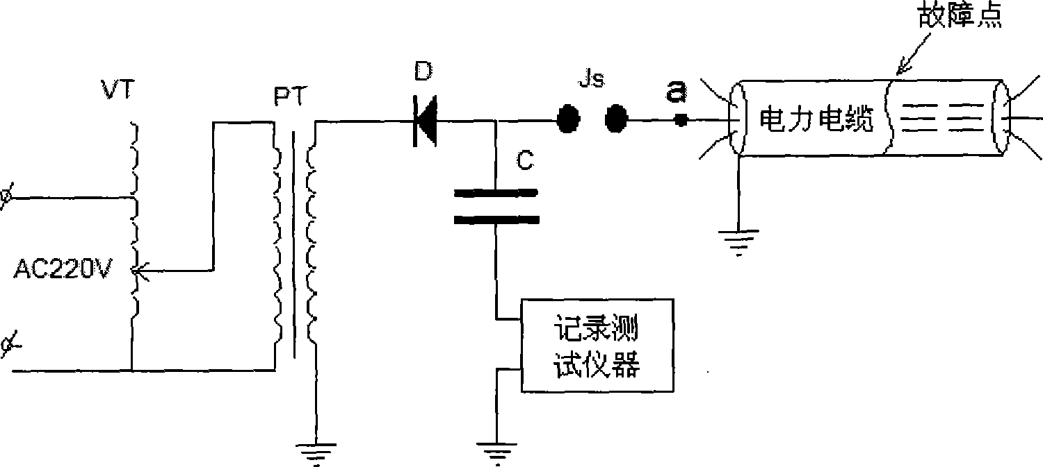
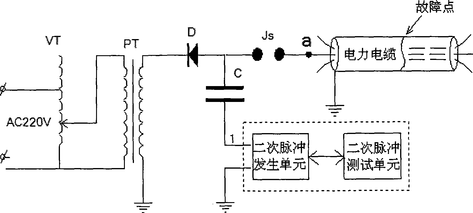
[0023] like figure 2 As shown, the test device of the present invention comprises a 20Kv high-voltage transformer PT whose input end is connected to the voltage regulator VT, and whose output end is connected to the first discharge ball of the energy storage capacitor C and the discharge ball gap Js through the rectifier diode D, and the discharge ball gap Js The second discharge ball is connected to the fault phase of the power cable through the test terminal a. A secondary pulse generating unit is connected in series between the ground terminal 1 of the energy storage capacitor C and the ground, and the secondary pulse generating unit is bidirectionally connected with the secondary pulse testing unit.

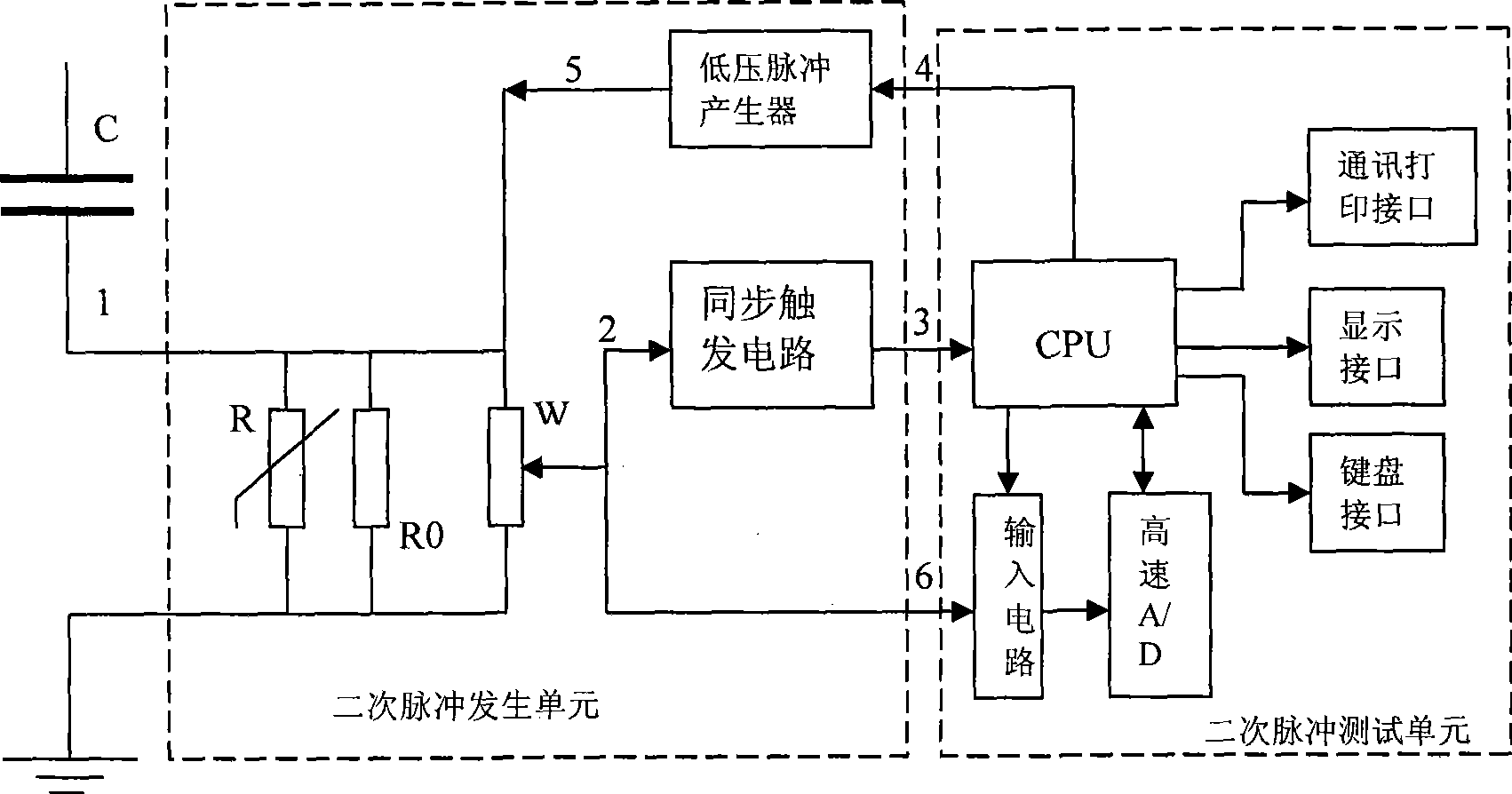
[0024] As shown in Figure 3, the secondary pulse generating unit includes a synchronous trigger circuit, a low-voltage pulse generator, a ...


PUM

PropertyMeasurementUnit
Amplitudeaaaaaaaaaa

Abstract

The invention discloses a method for detecting a power cable fault based on the two-time pulse mode. Compared with the prior detection method, the method is characterized in that the method organically combines the two prior pulse detection methods, namely the high voltage pulse detection method and the low voltage pulse detection method; and when DC high voltage is applied to various high resistance faults of the cable, the method does not record back and forth reflected waves self generated by the fault point, but according to the physical principle that the fault point is electrically discharged under the action of high voltage, and a short circuit fault is formed and kept for a period of time, and adds the two-time low voltage pulse to the fault phase of the cable during the period of time, thereby forming a detection waveform with little interference and strong identification like a low voltage method, and consequently detecting various high resistance faults of the power cable effectively.

Description

technical field [0001] The invention belongs to a detection method for a power cable fault, in particular to a method for detecting a power cable fault based on a secondary pulse method. Background technique [0002] When detecting power cable faults, the existing mature technology is based on the principle of pulse reflection based on traveling wave theory (that is, the principle of radar reflection). There are two common methods: low-voltage pulse method; high-voltage pulse method (flashover method). The low-voltage pulse method is mainly used to detect open-circuit faults and low-resistance short-circuit faults in cables, but these two types of faults are relatively rare in practice, so the low-voltage pulse method is less applicable to fault types. The high-voltage pulse method is mainly used to detect various types of high-resistance faults other than the above two types of faults, that is, by applying DC high voltage (several Kv to hundreds of Kv) to the faulty phase ...

Claims


Application Information

Patent Timeline
IPC IPC(8): G01R31/11
CPCY04S10/522Y04S10/52
Inventor 韩伯锋许东
Owner 西安四方机电有限责任公司
Why Eureka
Try Eureka