
Terminal landing speed control system of elevator

A technology for controlling the system and layer speed, applied in elevators, transportation and packaging, etc., can solve the problems of complex car position detection and other problems, and achieve the effect of simple structure

Inactive Publication Date: 2009-05-20
TOSHIBA ELEVATOR KK
View PDF1 Cites 11 Cited by
  • Summary
  • Abstract
  • Description
  • Claims
  • Application Information

AI Technical Summary

Problems solved by technology

[0005] However, in the conventional system, in order to detect the position of the car in the deceleration zone, it becomes a complicated structure in which many detection switches or devices corresponding thereto are provided (see FIG. 7 of Patent Document 1).
Furthermore, it is necessary to calculate the position of the car between each detection switch by using an arithmetic method such as linear interpolation, and the detection of the position of the car is also complicated.

Method used


Image

  • Terminal landing speed control system of elevator
  • Terminal landing speed control system of elevator
  • Terminal landing speed control system of elevator

Examples


Embodiment Construction

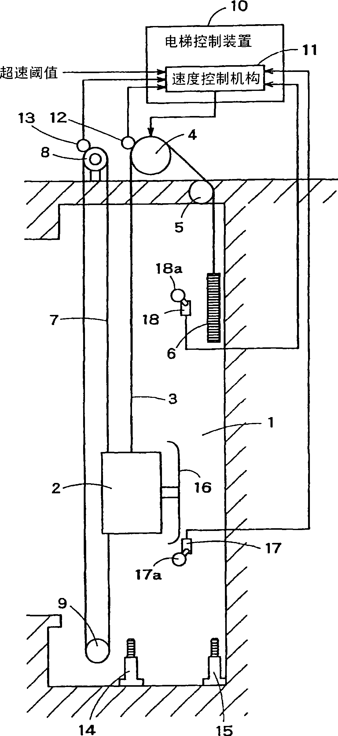
[0022] figure 1 It is a configuration diagram of an elevator terminal floor speed control system according to an embodiment of the present invention. A lift passage 1 is formed in a building, and a car 2 can move up and down in the lift passage 1 . One end side of a main rope 3 is attached to the car 2 . The middle portion of the main rope 3 is wound around a hoist 4 installed in a machine room, and the other end thereof is attached to a counterweight 6 via a deflector pulley 5 .

[0023] On the other hand, one end side and the other end side of the adjuster rope 7 are attached to the car 2 . The adjuster rope 7 is wound through an adjuster 8 and an adjuster pulley 9 .

[0024] The hoist 4 is controlled by a speed control mechanism 11 provided in the elevator control device 10 . The speed control mechanism 11 inputs the detected driving speed from the speed detectors 12, 13 respectively installed on the hoist 4 and the regulator 8, and compares it with the preset overspeed...


PUM


Abstract

When an elevator car descends to cause a contact plate to be in contact with an actuator section, a limit switch outputs a car detection signal to speed control means. Then, the speed control means compares overspeed thresholds set according to the distance from a deceleration start position (position where the limit switch is placed) and detected travel speed from a speed detector. When the detected travel speed exceeds an overspeed threshold, the control means forcibly decelerates the car to stop it.

Description

technical field [0001] The invention relates to a terminal floor speed control system of an elevator. Background technique [0002] When the elevator car travels from the departure floor to the destination floor, it gradually decelerates after passing through the deceleration start position set near the destination floor, and stops at the stop position of the destination floor through the subsequent stop control. This is to prevent the car from violently colliding with the uppermost or lowermost part of the elevator passage if the deceleration period is not sufficiently decelerated due to some abnormality when the destination floor is the terminal floor (the uppermost floor or the lowermost floor). The lowermost case. [0003] In order to avoid such a situation, in a normal elevator system, when the car overspeed is detected in the deceleration section from the deceleration start position to the stop position, the brake is applied to forcibly decelerate and stop the car. F...

Claims


Application Information

Patent Timeline
IPC IPC(8): B66B5/06
CPCB66B1/48B66B1/28B66B5/0006
Inventor 三岛浩一前田真吾
Owner TOSHIBA ELEVATOR KK
Learn More